Sign in



Why are serpentine traces designed on the NIC PCB board
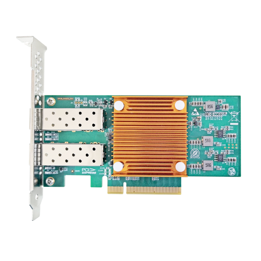
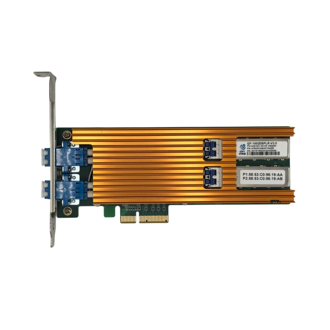
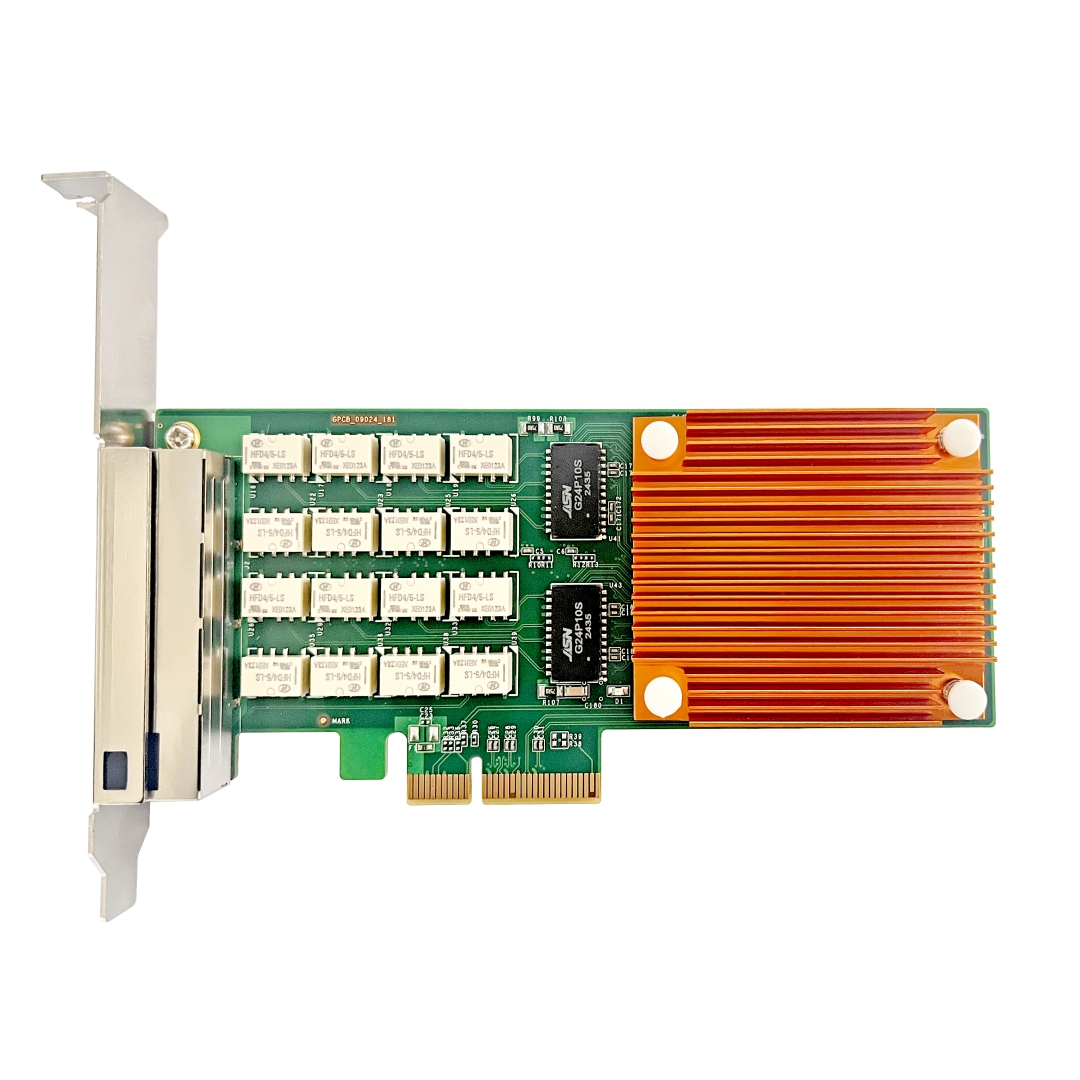
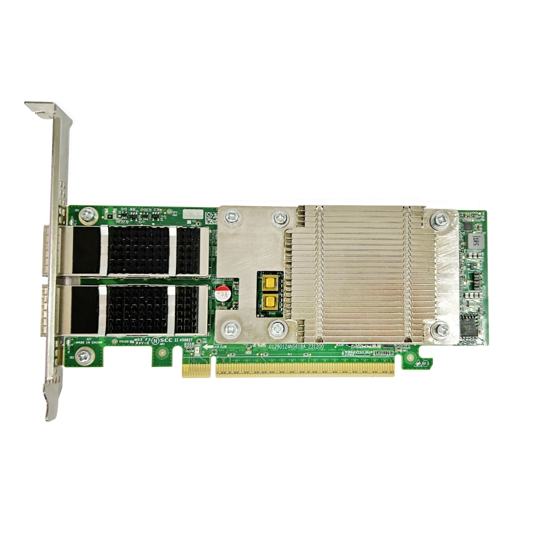
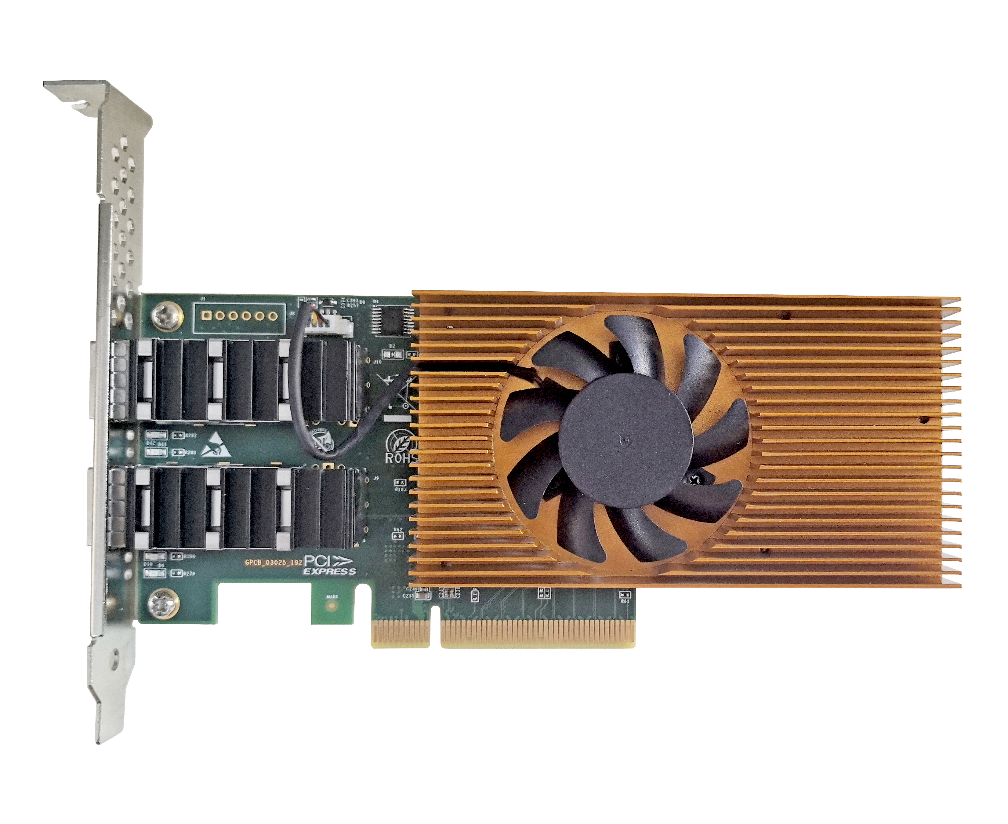
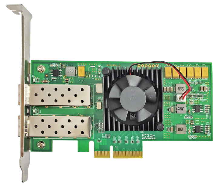
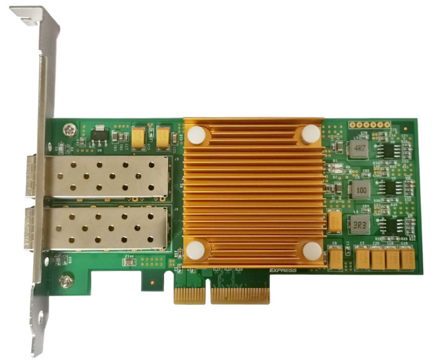
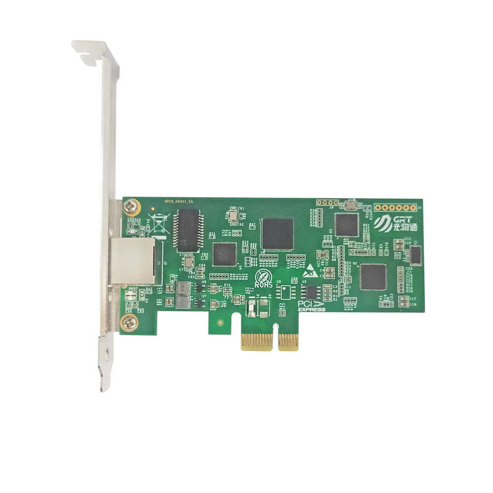
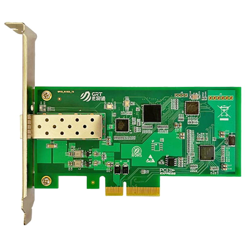
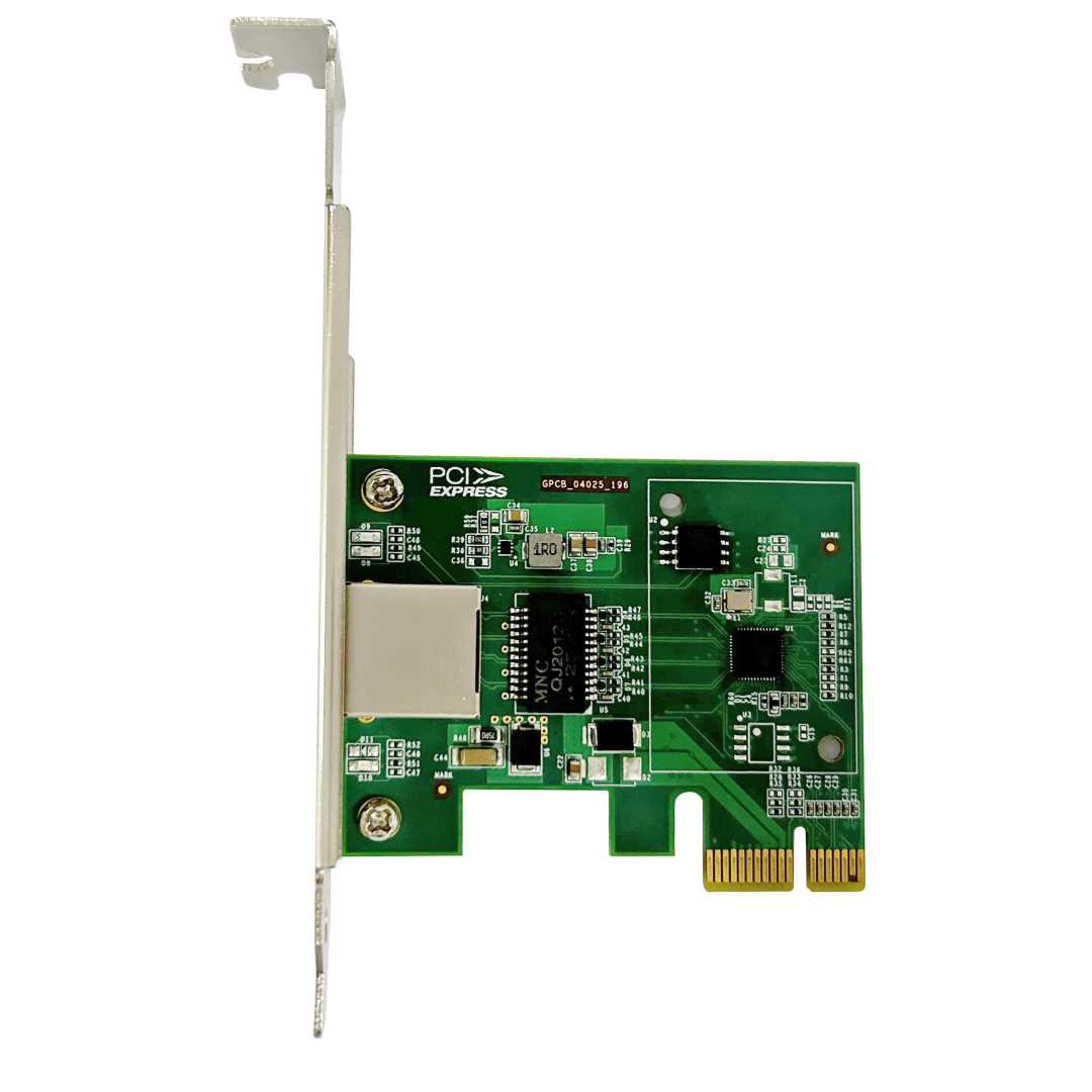
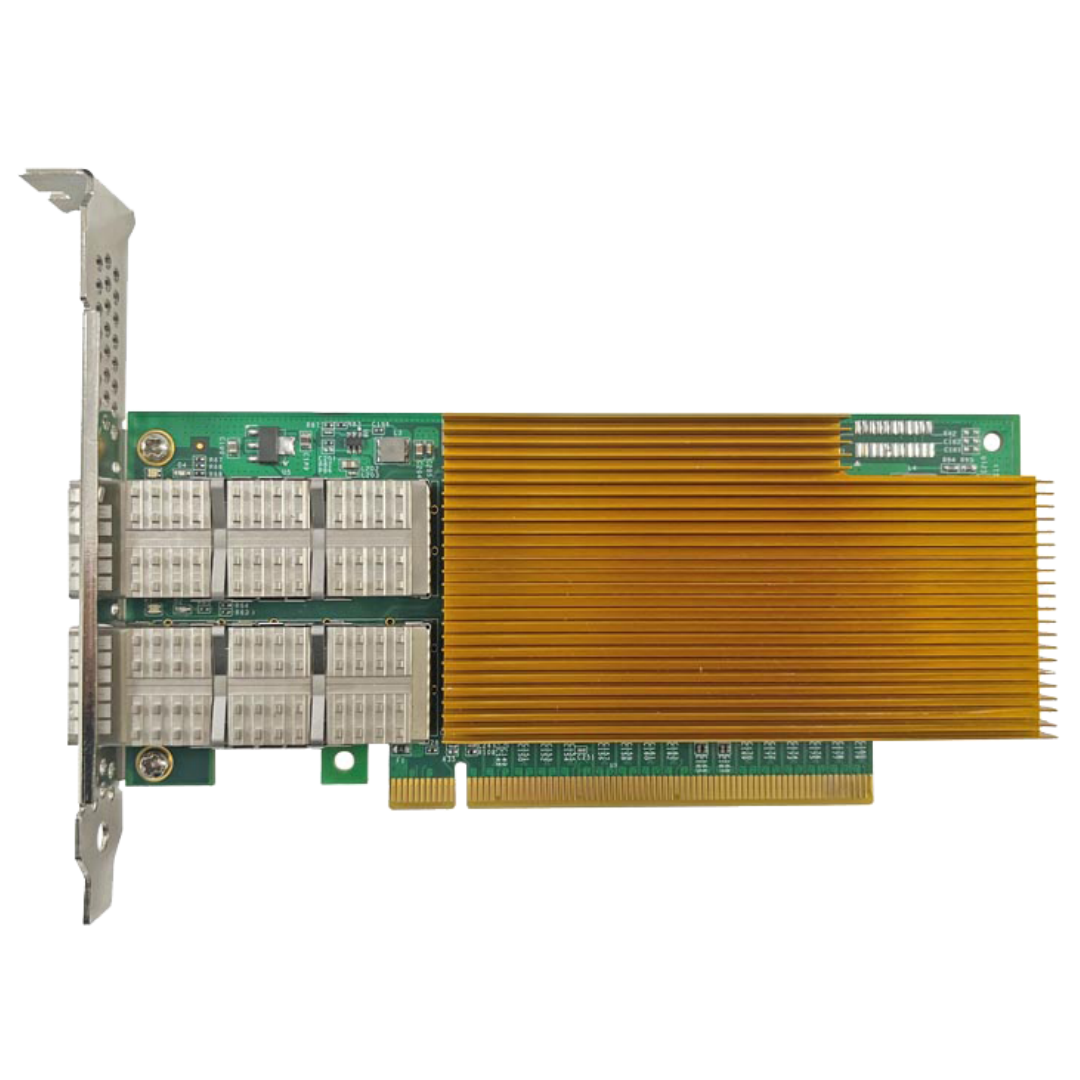
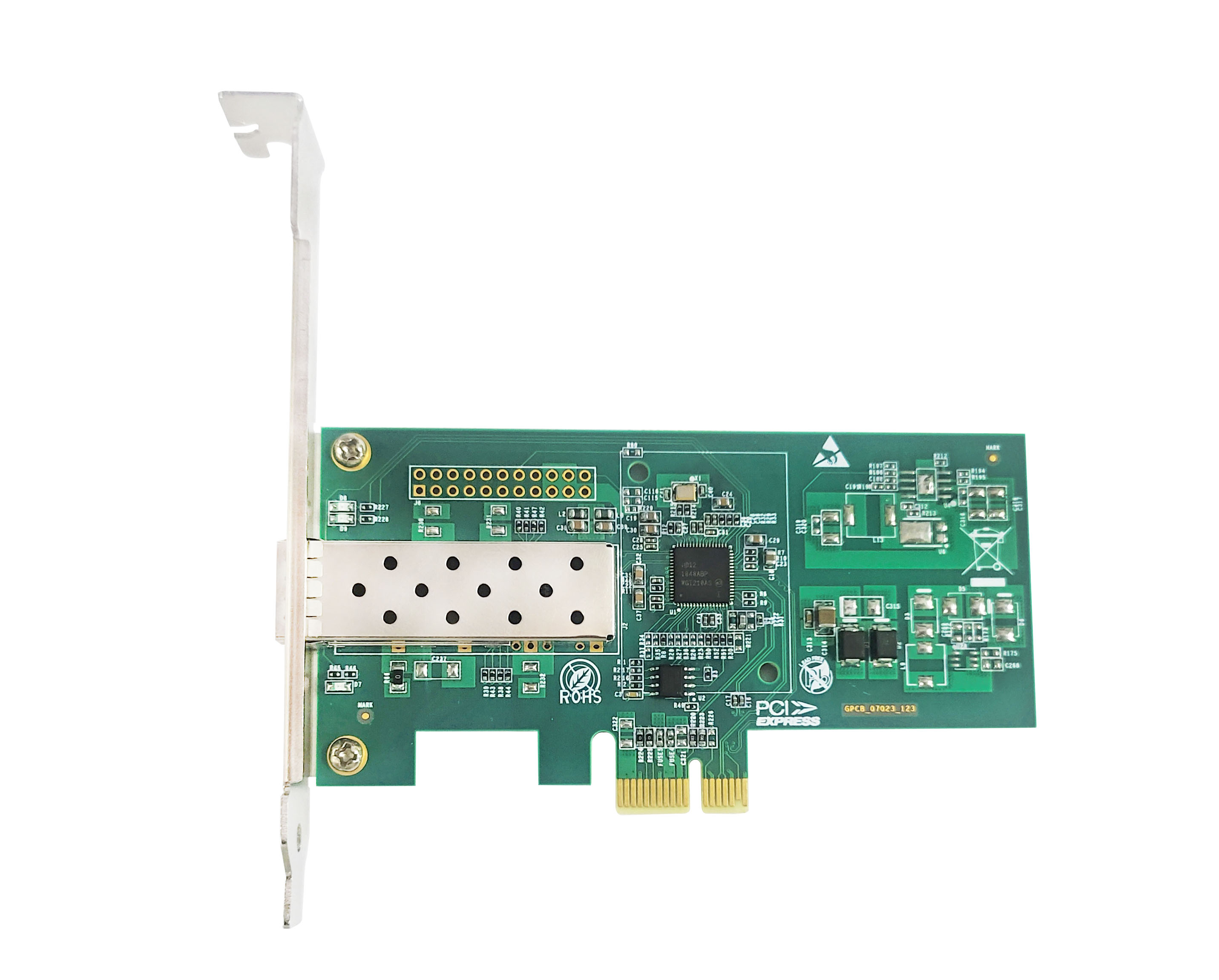
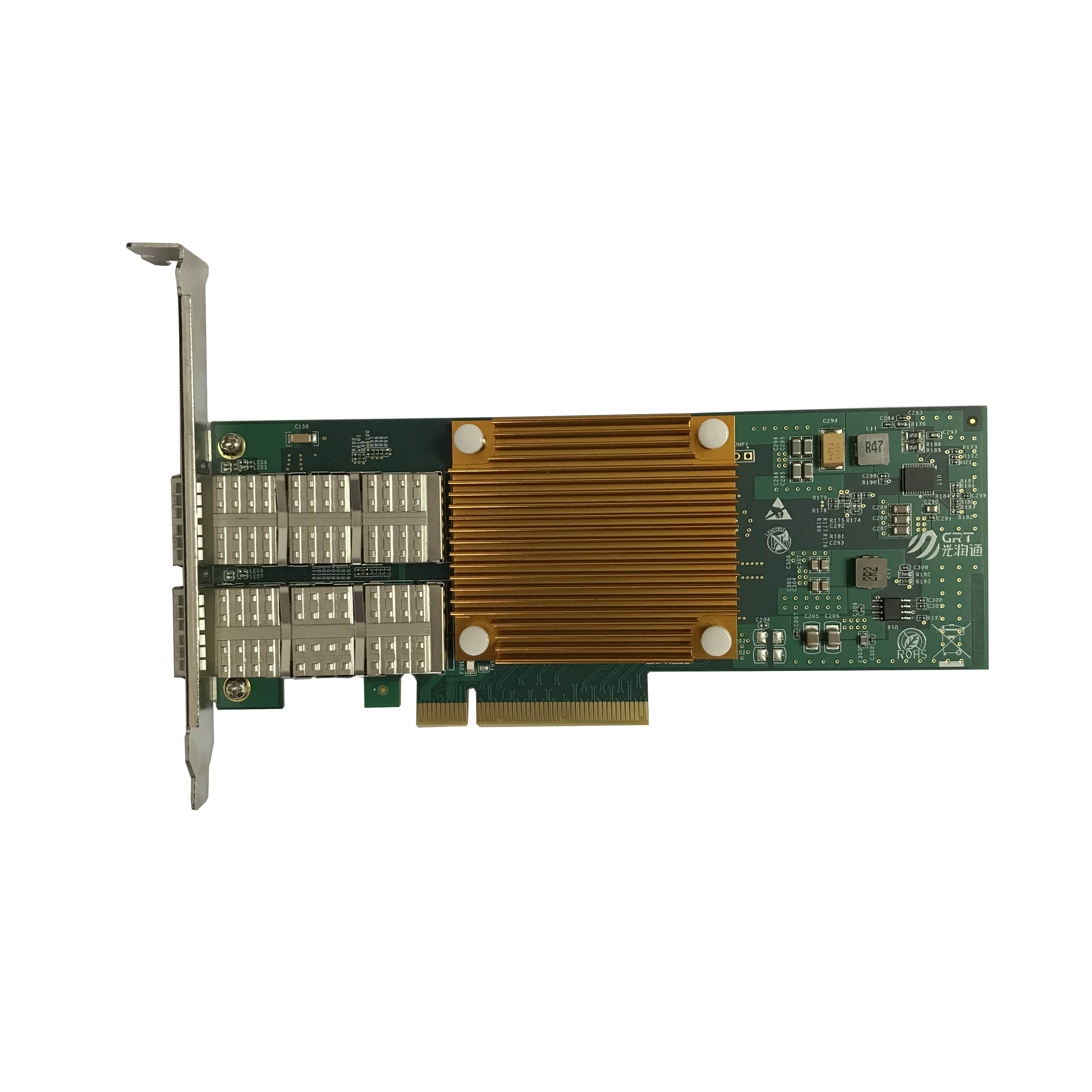
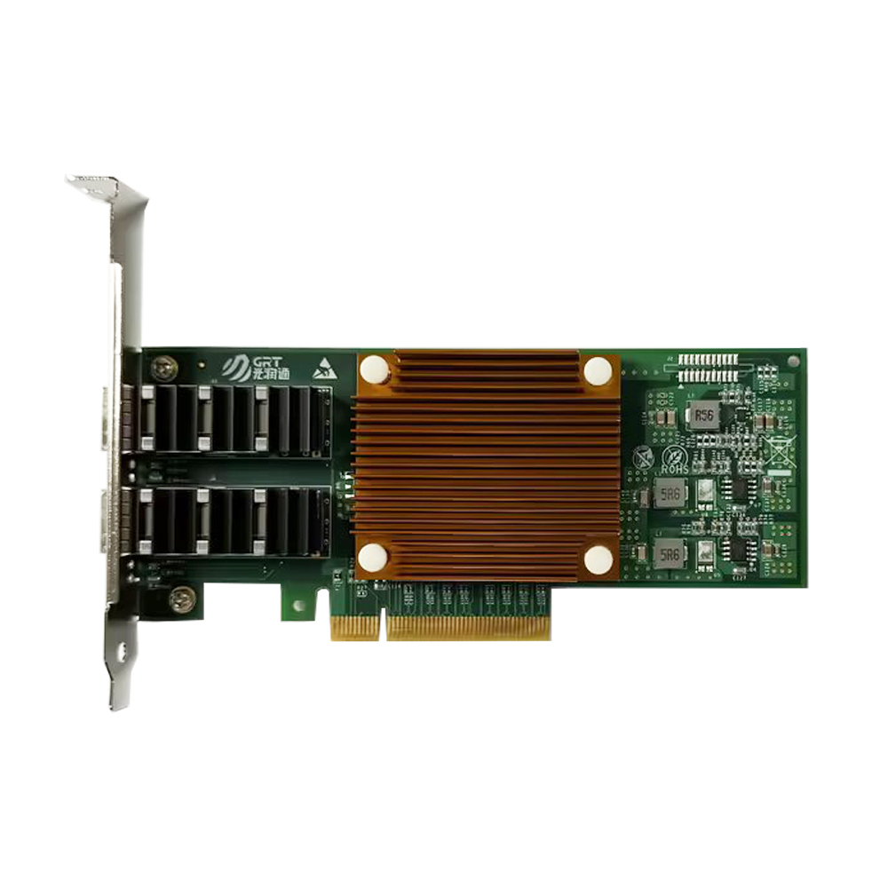
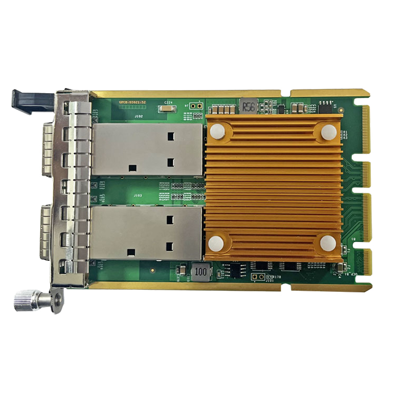
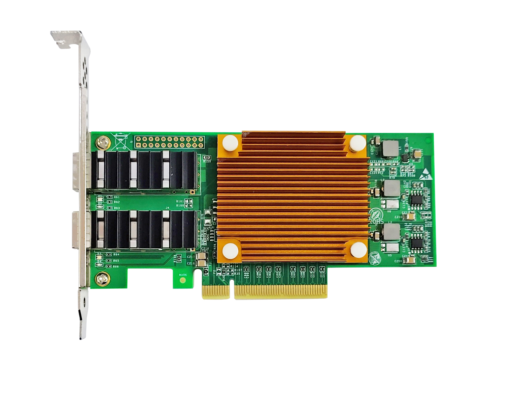
< BackIn the circuit board design of fiber network adapters, careful observation reveals that some signal lines are not straight but feature regular serpentine bends. This design is not for aesthetic purposes, but a necessary method to guarantee signal integrity in high-speed digital circuits. The core purpose of serpentine traces is to achieve length matching for the same group of signal lines, so as to control the time deviation when signals arrive at the receiving end.
In high-speed transmission, the propagation speed of electrical signals on PCB depends on the dielectric constant of the board material. Taking standard FR-4 material as an example, its dielectric constant is about 4.2, and the signal propagation speed is approximately 0.49 times the speed of light, which is around 14.7 centimeters per nanosecond. By conversion, it takes roughly 0.068 nanoseconds for a signal to travel 1 centimeter. For PCIe 3.0 interface (8GT/s rate), one bit time period is 125 picoseconds (0.125 nanoseconds). If the length difference between two lines in the same group of data cables reaches 1.8 cm, the time skew will exceed one bit period and cause data sampling errors at the receiver. Therefore, the PCIe bus specification requires the length difference between data lines in the same group to be controlled within tens of mils (1 mil = 0.0254 mm), namely no more than 0.5 to 1 cm.
Serpentine traces add detour paths on shorter lines to make the total length of signal lines in one group consistent. For instance, the shortest wire in a data group may need two serpentine bends to add about 5 mm path length to match the longest wire. Nevertheless, more serpentine traces do not equal better performance. Excessive winding introduces extra parasitic capacitance and inductance, slowing down the signal rising edge and increasing crosstalk, which degrades signal quality instead. Experimental data shows that each set of serpentine bends may reduce the eye diagram opening by 5% to 10%. Thus, premium designs minimize winding length and bends while meeting length matching tolerances.
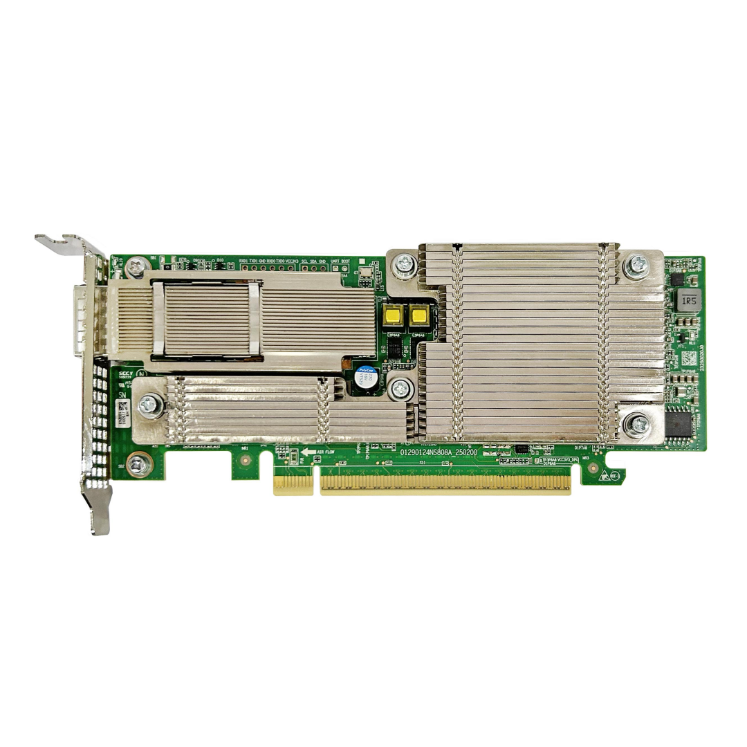
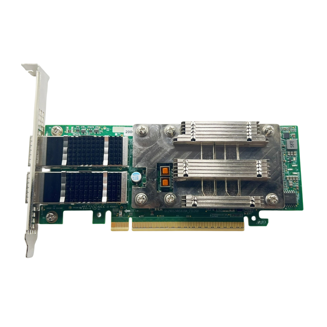
The traces of Guangruntong (GRT) network adapters are designed with comprehensive and rigorous evaluation. Hardware engineers use professional high-speed design software for pre-simulation and post-simulation, precisely controlling the impedance of each signal line (typically within ±10%) and time delay matching. By optimizing trace topology and stack-up structure, Guangruntong (GRT) ensures length matching and minimizes the adverse effects brought by serpentine traces. This strict design workflow guarantees signal integrity and long-term stable operation of network adapters at 100G and even higher speeds.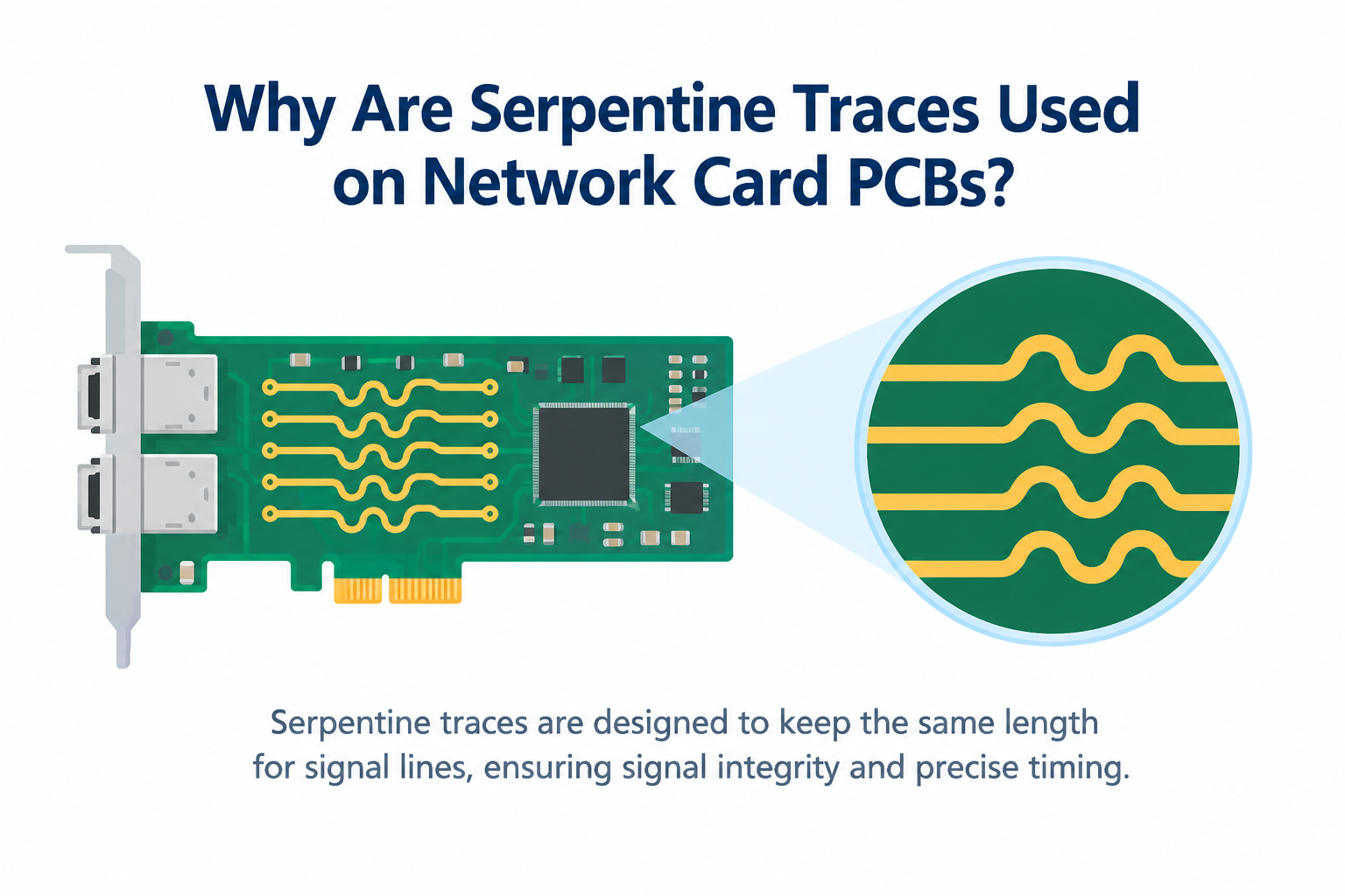
Latest information
- Why are serpentine traces designed on the NIC PCB board
- NIC and Operating System Ecosystem Adaptation: From Hardware Compatibility to Win-Win Performance
- NIC Hardware Offload Technology: Let Server CPU Focus on Business Computing
- Network Card Driver: The Invisible Bridge Between Hardware and Operating System
- Understanding the Partners in Fiber Links: Optical Modules and Optical Fibers
- How to Select NICs for Virtualization Environments to Achieve Performance Isolation and Resource Allocation
- What are FCC, CE and RoHS on Network Cards
- How Bypass NIC Ensures Uninterrupted Network When Server Power Fails