Sign in



The Hidden Relationship Between NIC Heat Dissipation and Data Center Cabinet Layout
< BackThe Hidden Relationship Between NIC Heat Dissipation and Data Center Cabinet Layout
In data center operations, heat dissipation issues are usually attributed to air conditioning systems, hot/cold aisle containment or server fan policies. However, an easily overlooked detail: as an important heat source inside servers, fiber optic network adapters have thermal performance closely linked to cabinet layout. When poor cooling causes the NIC chip temperature to rise excessively, speed throttling protection will be triggered, resulting in reduced network throughput, latency jitter or even intermittent link drops. Understanding NIC thermal rules helps optimize cabinet deployment and improve network stability.
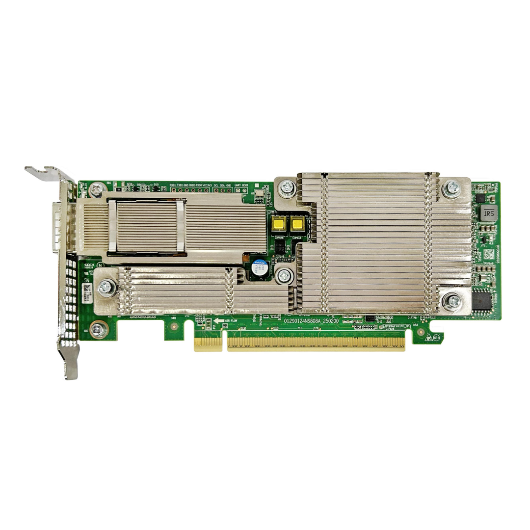
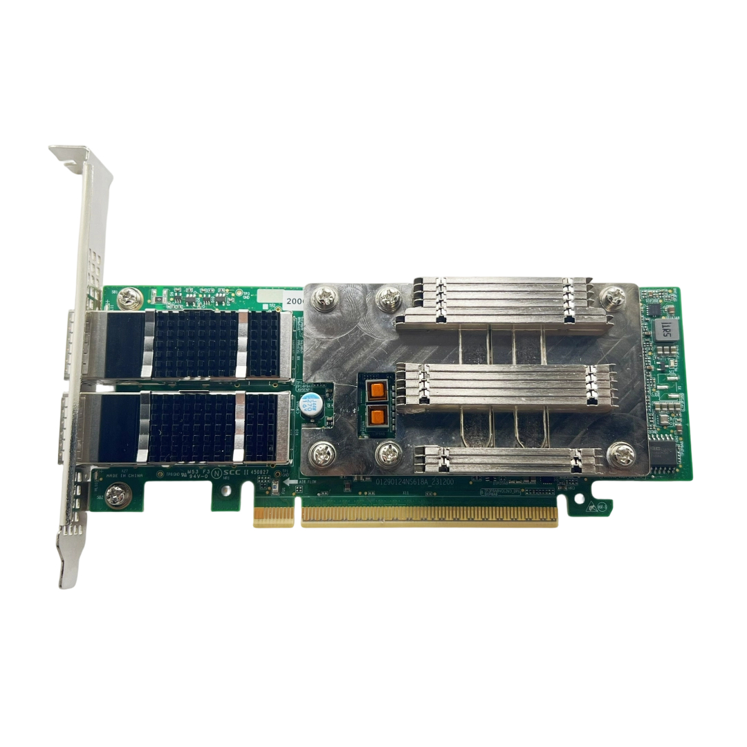
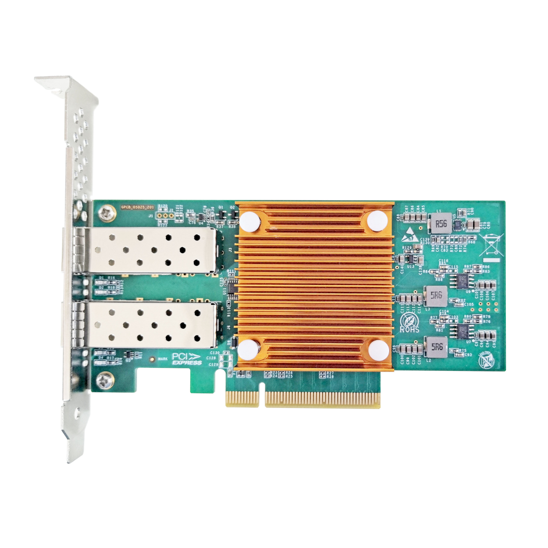
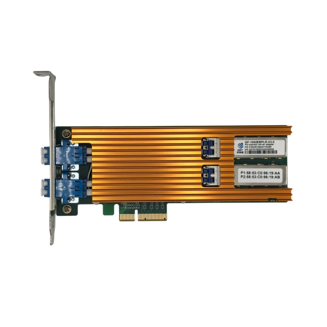
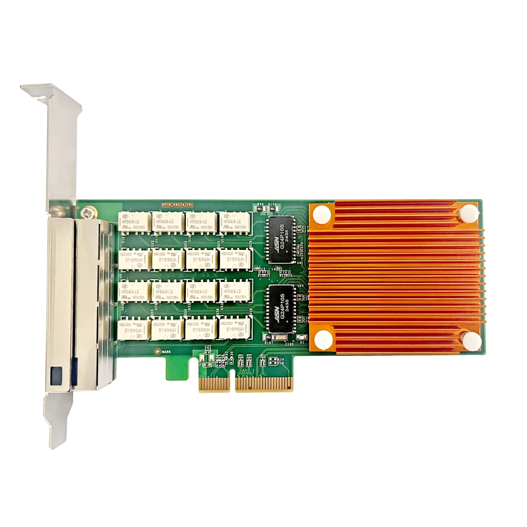
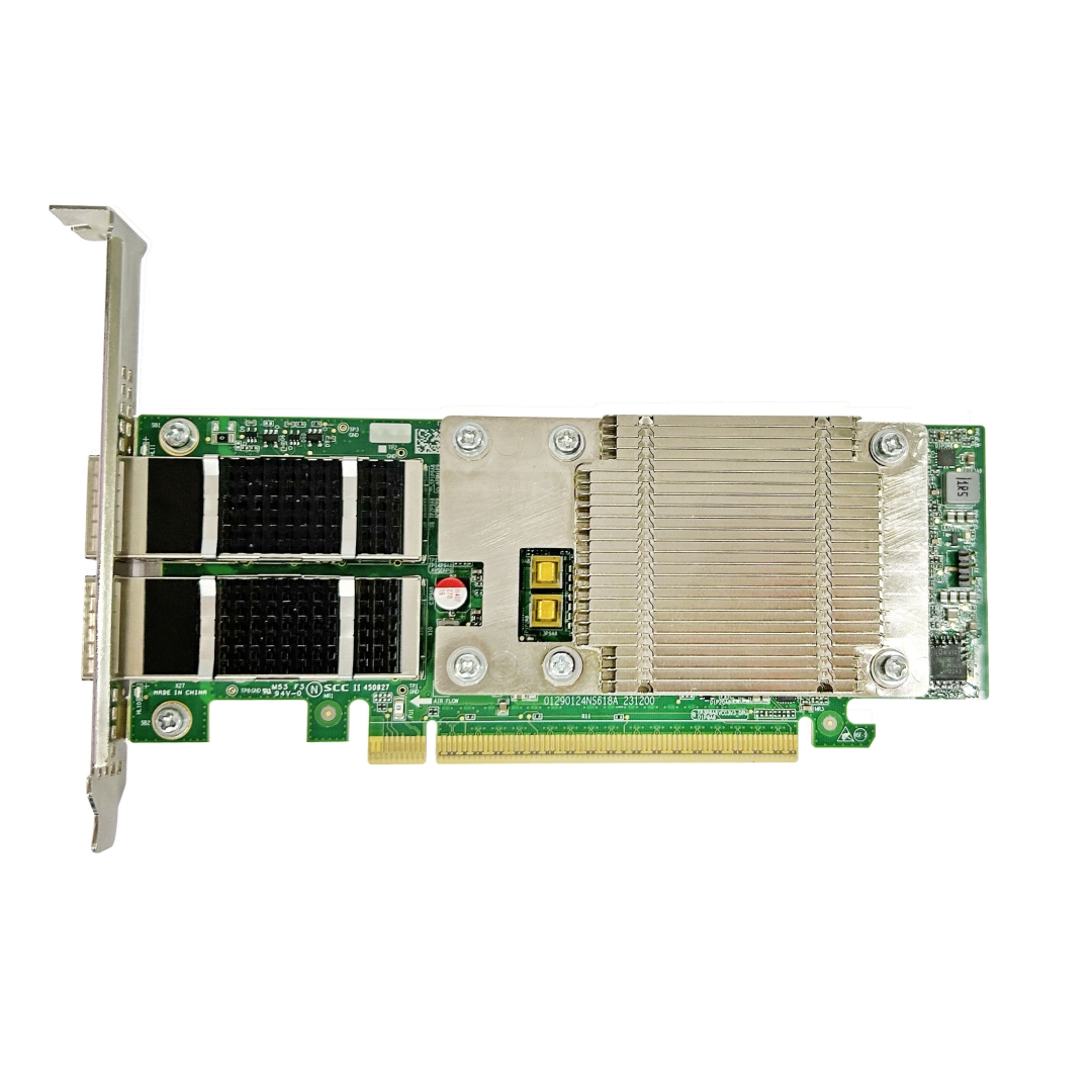
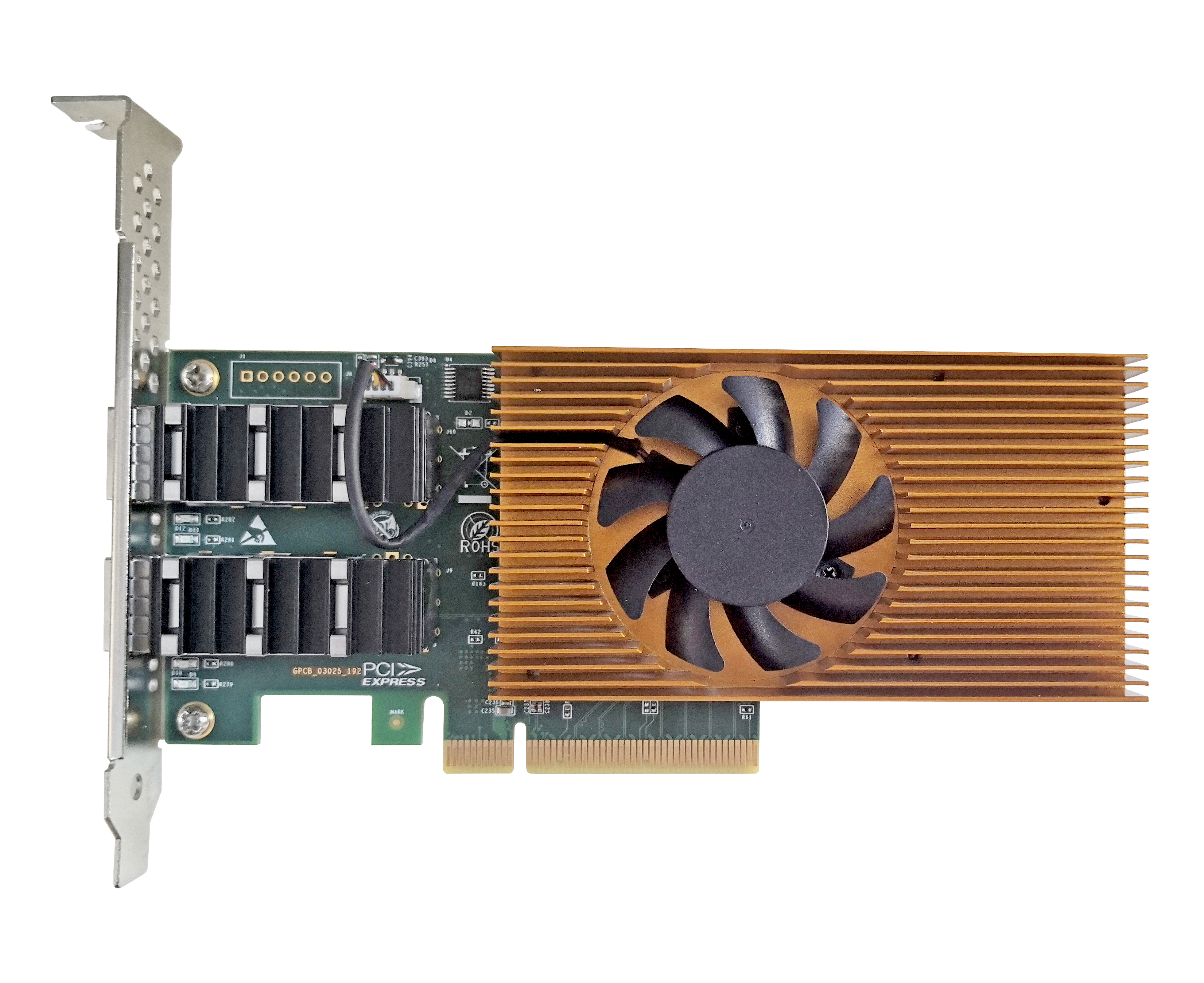
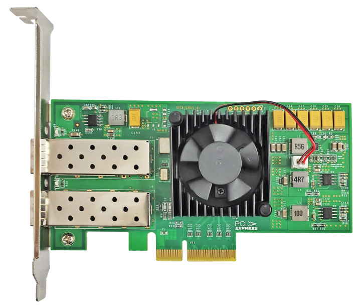
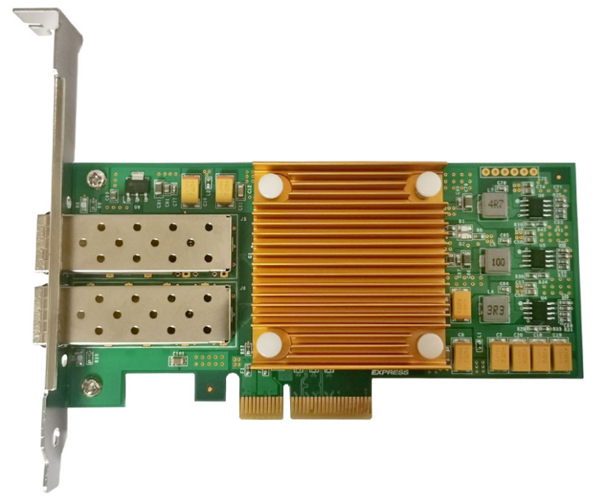
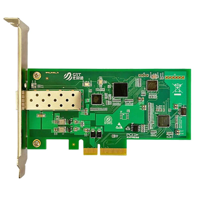
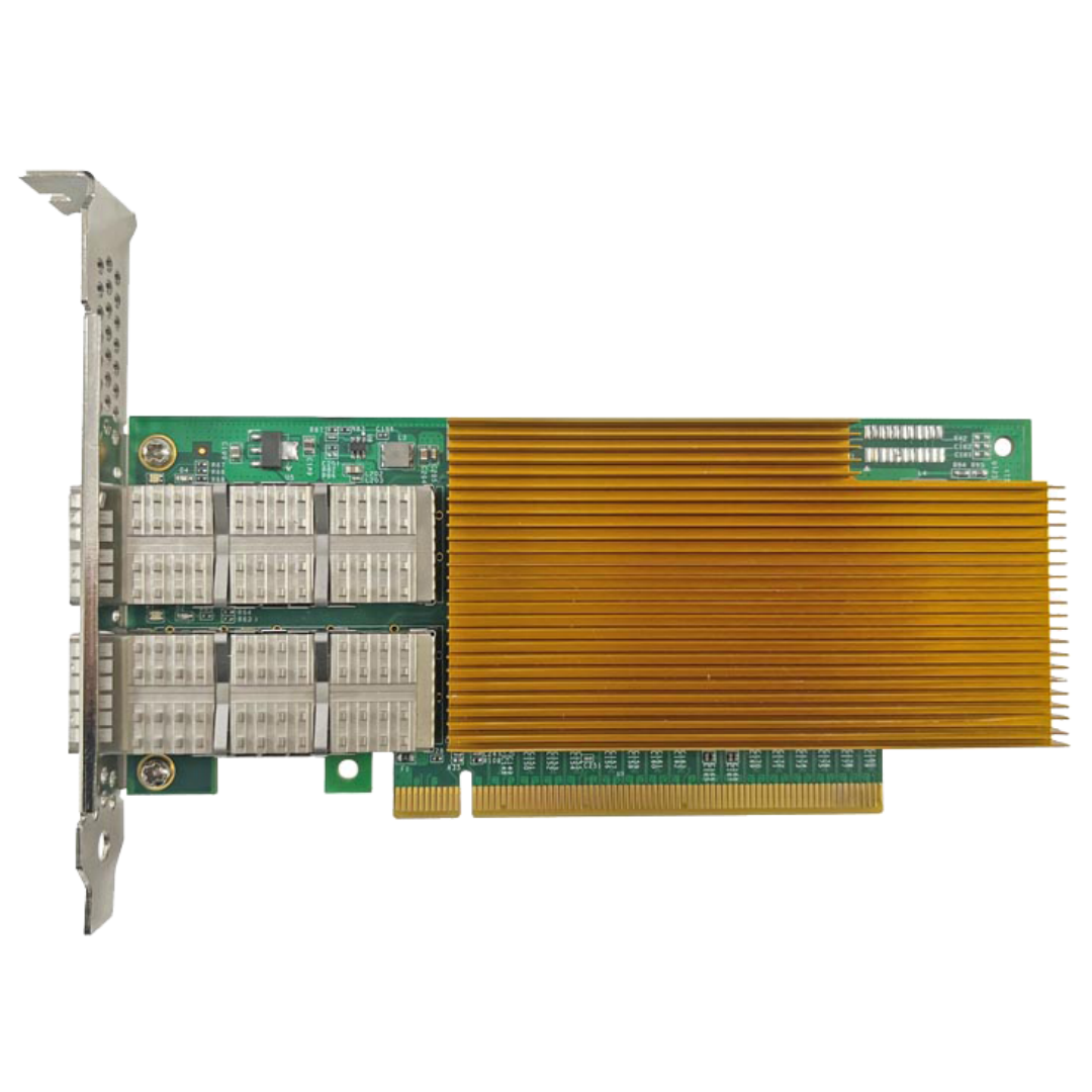
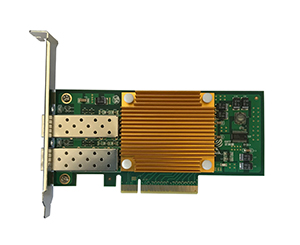
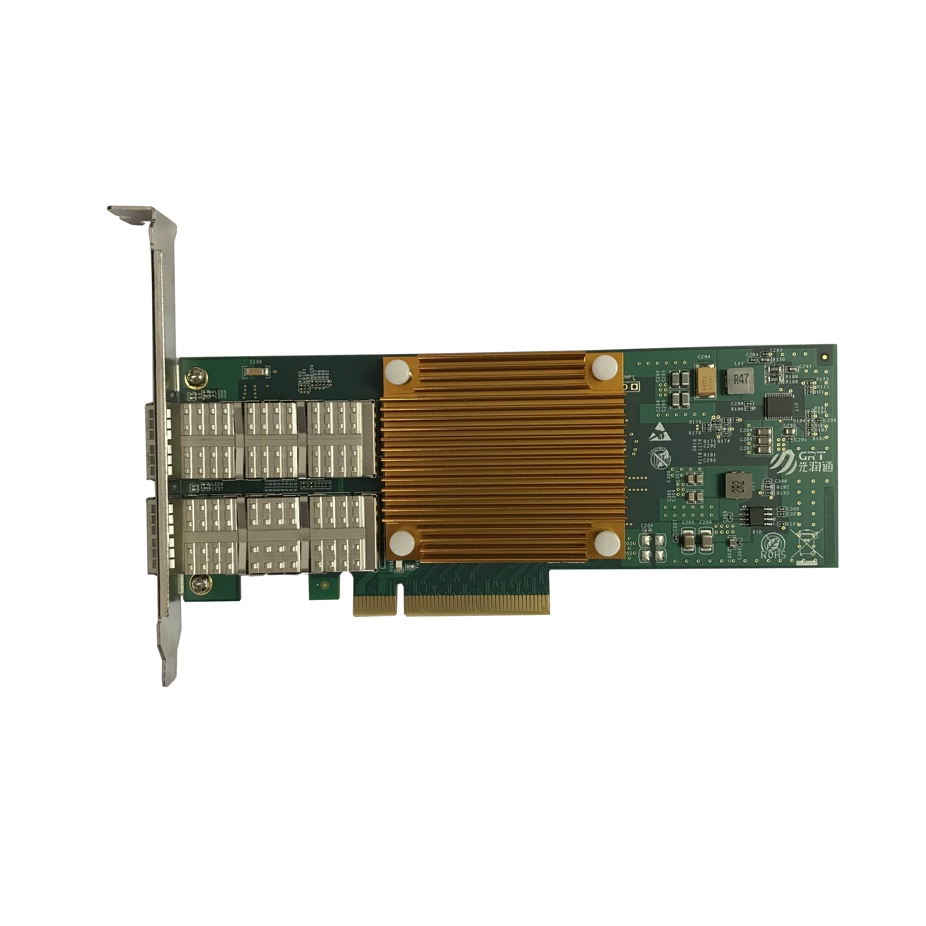
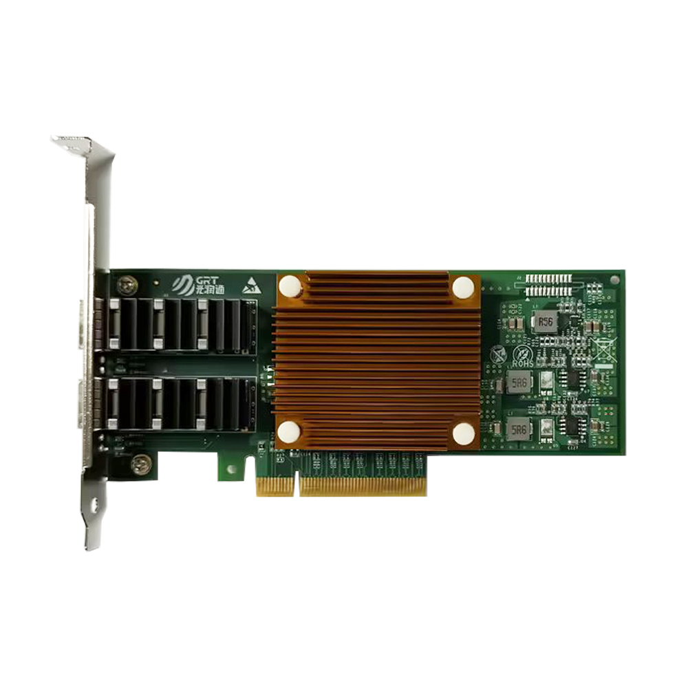
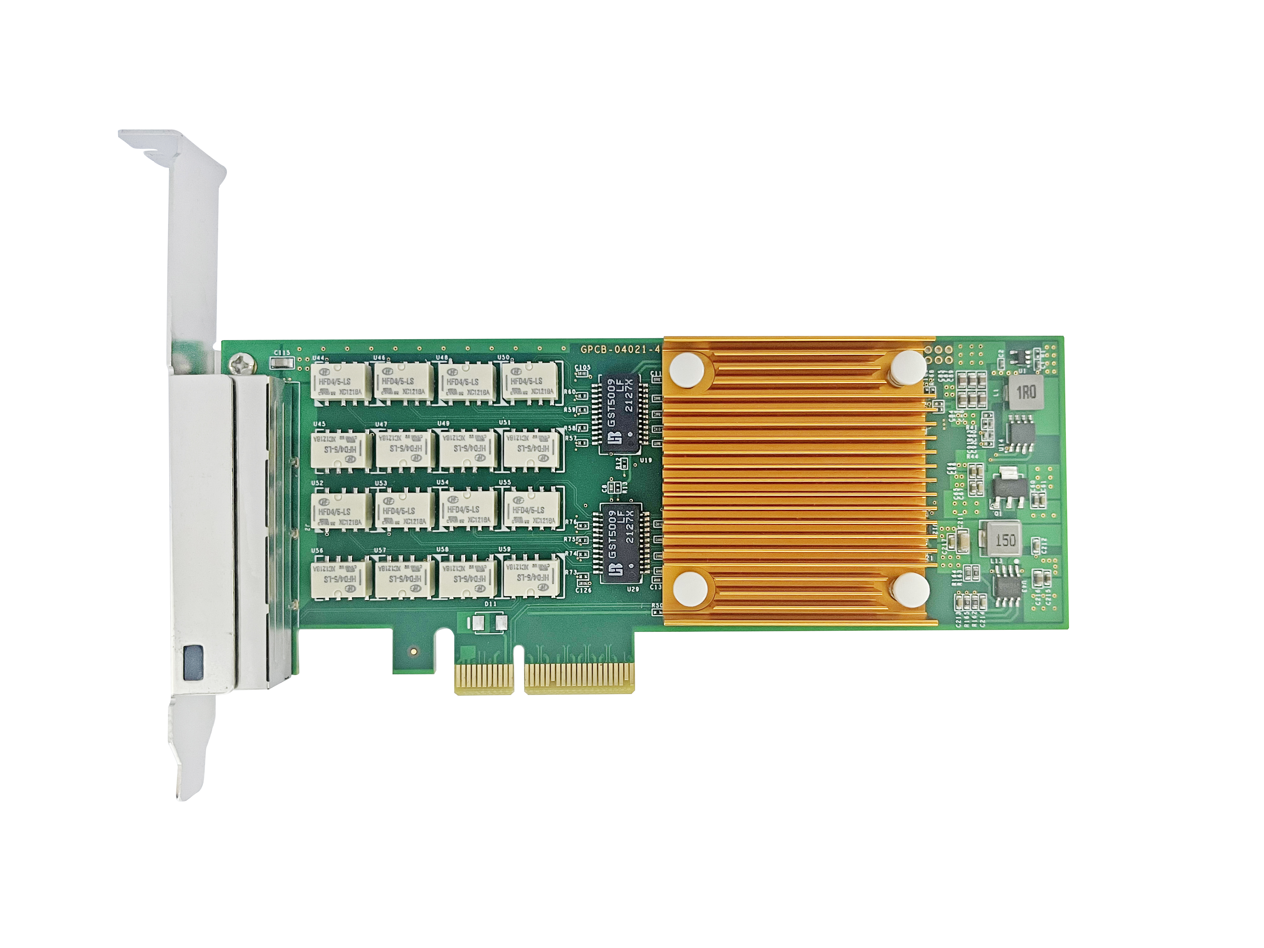
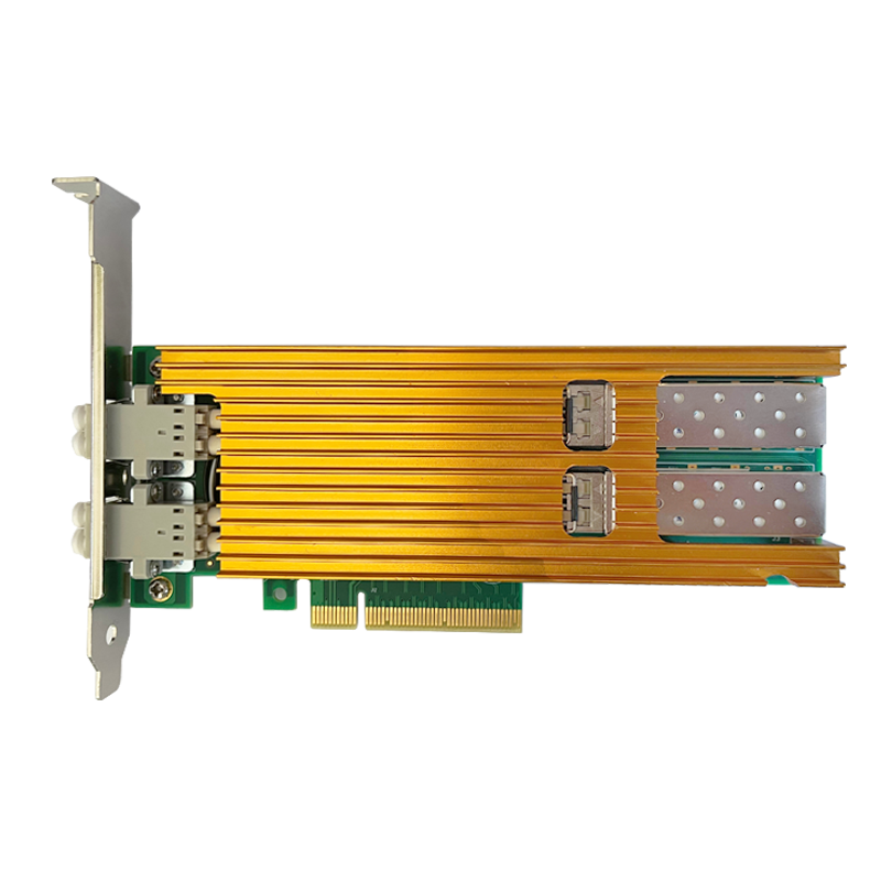
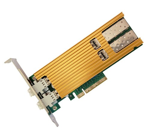
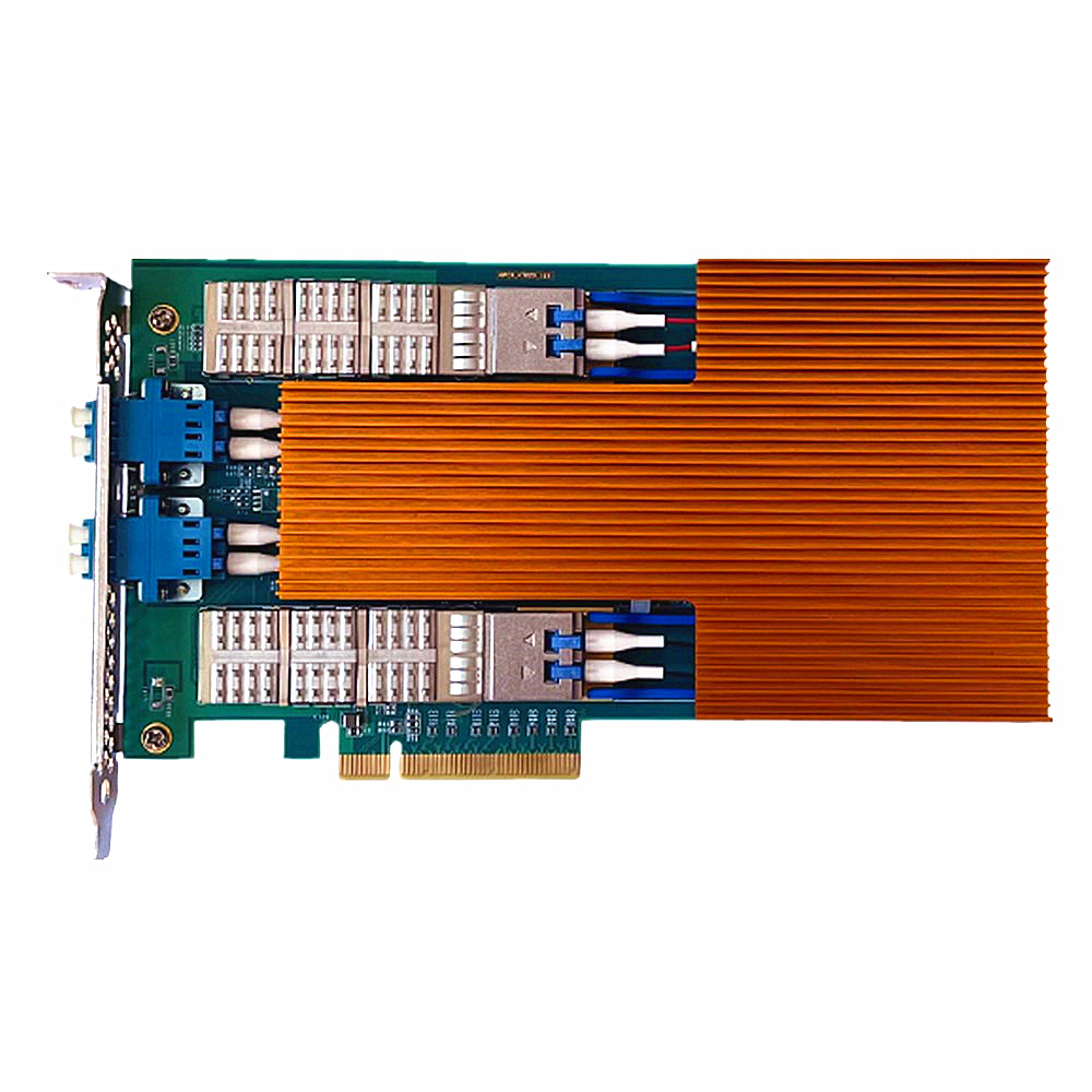
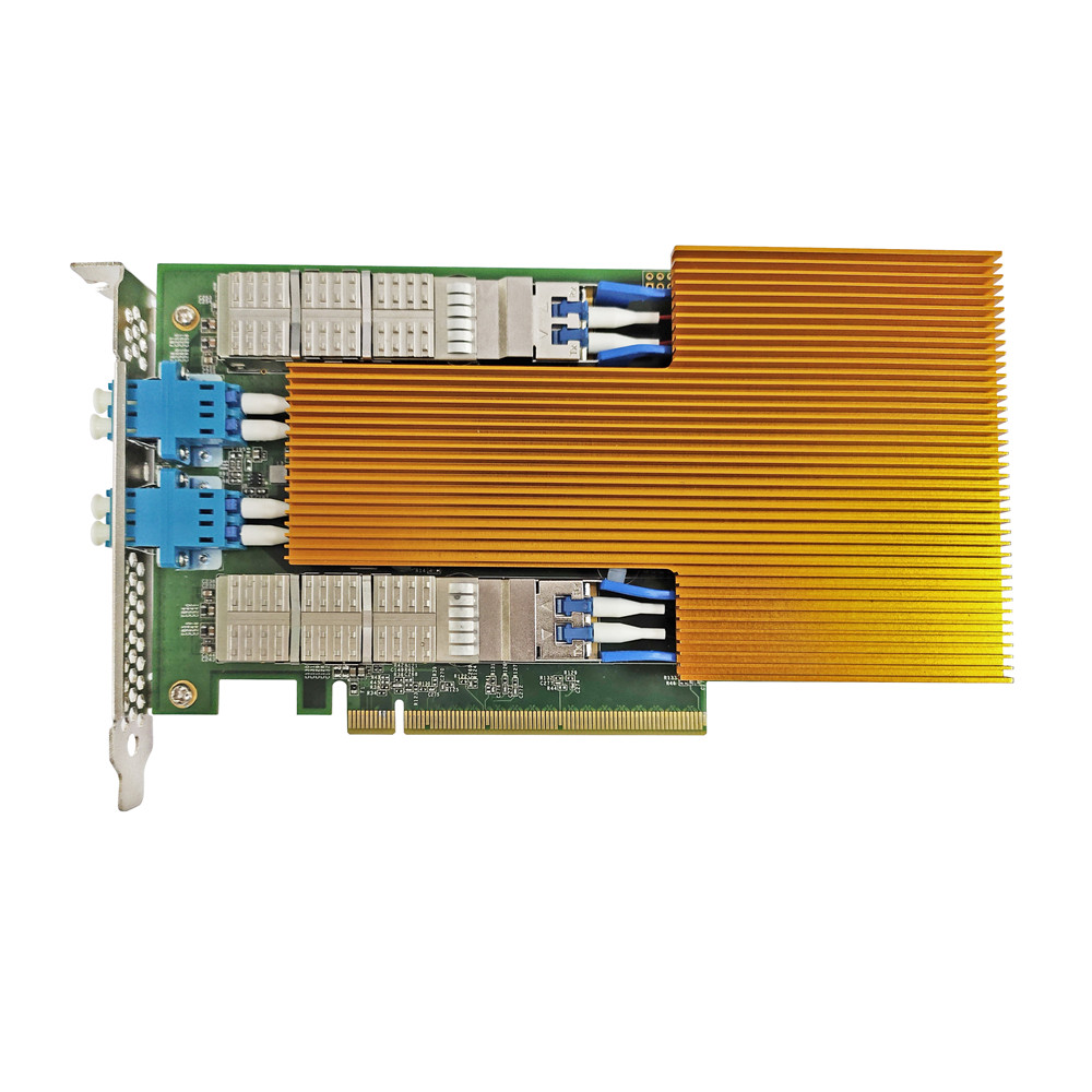
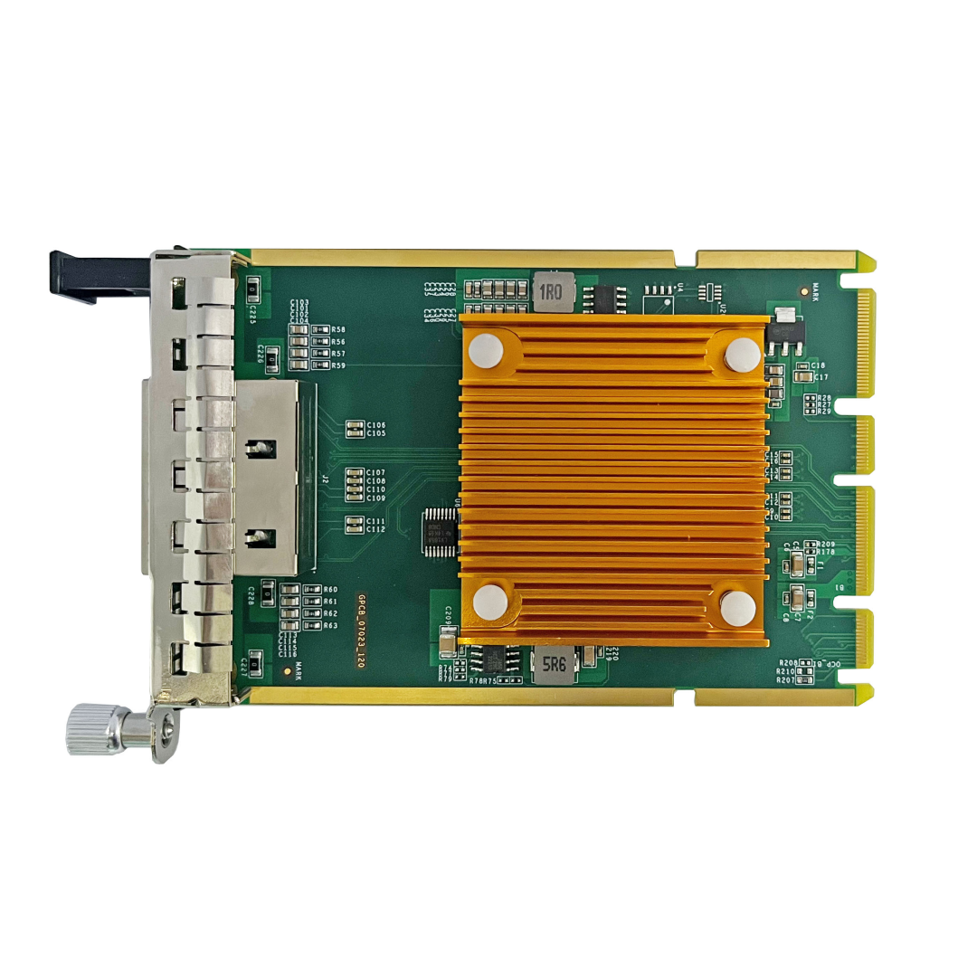
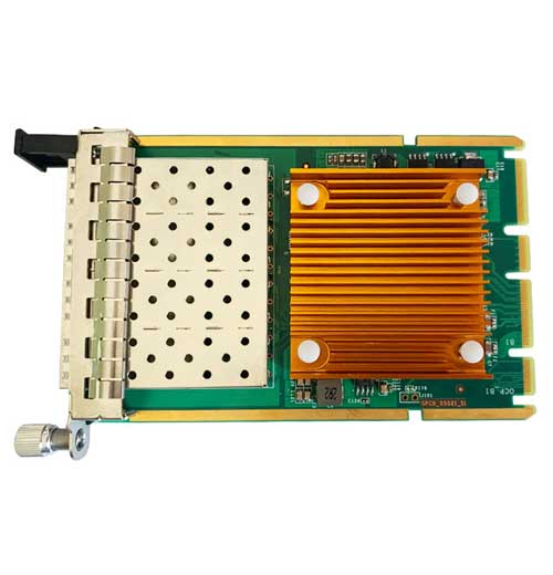
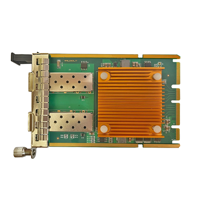
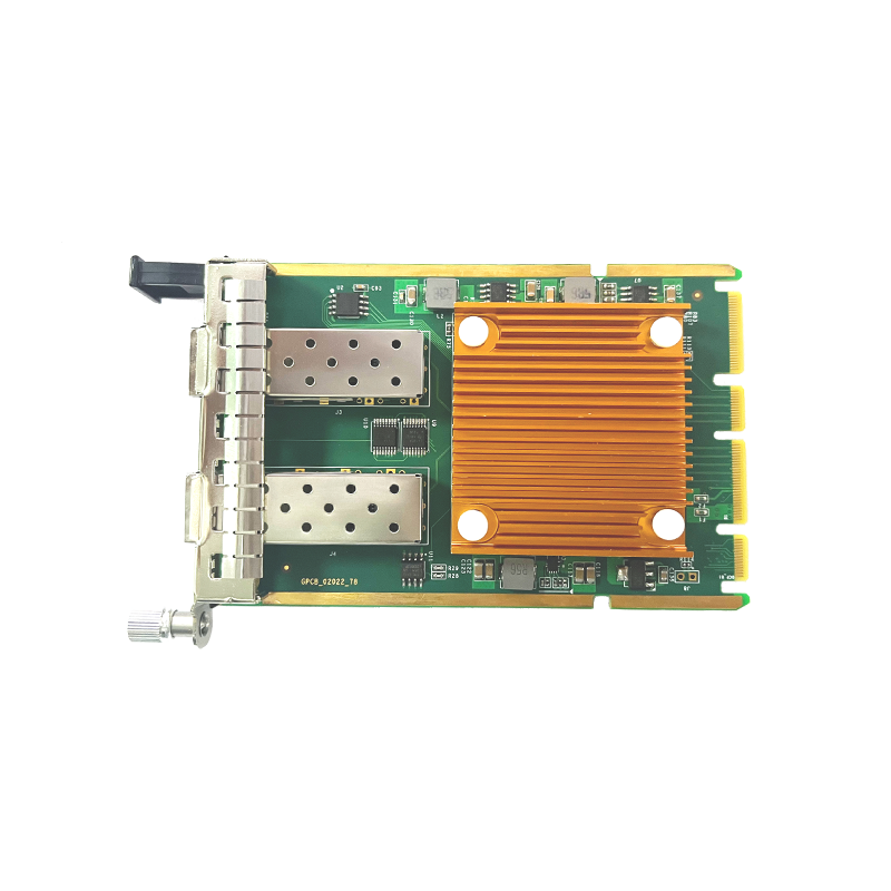
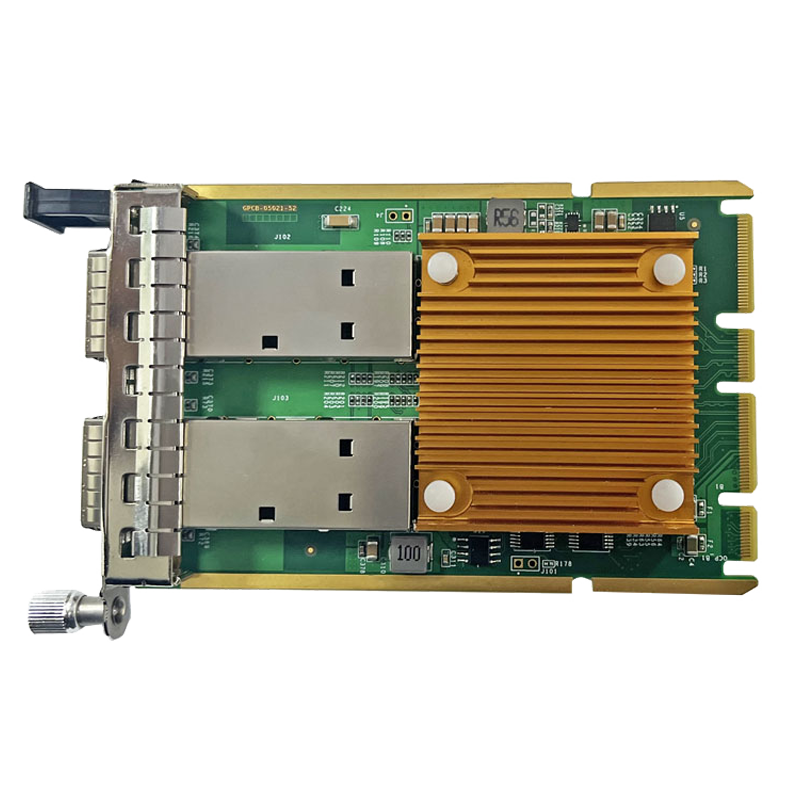
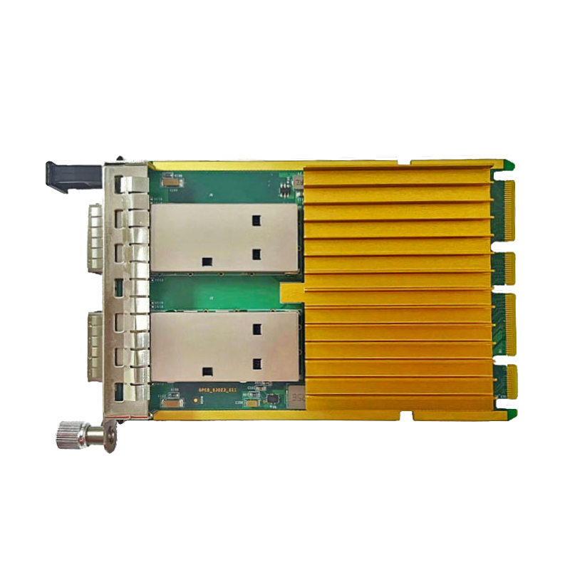
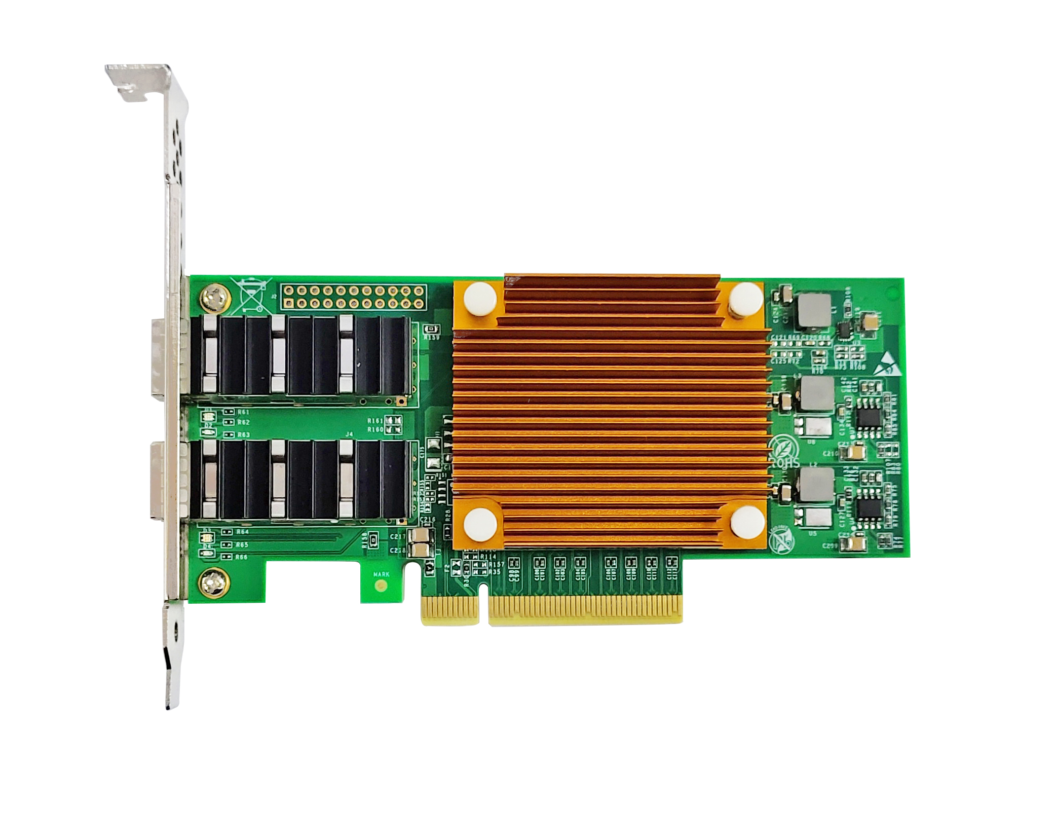
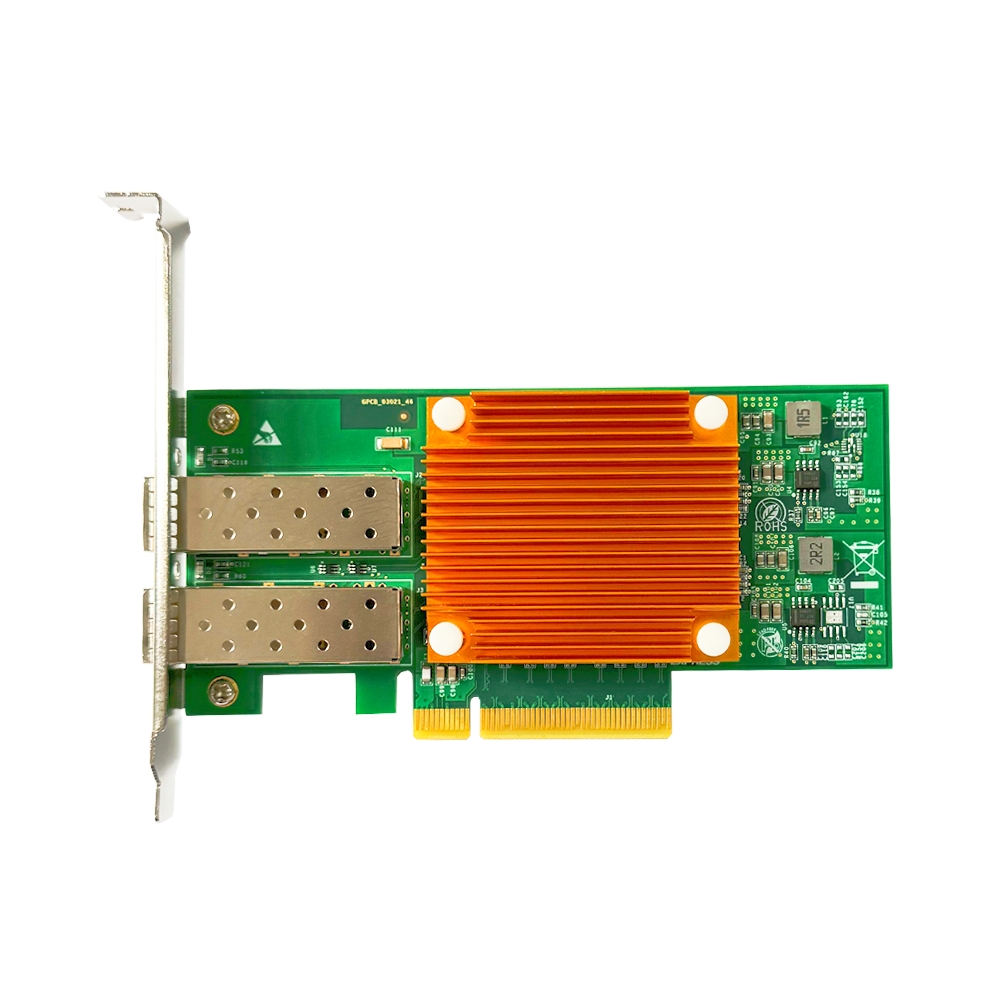
Heat generation of fiber NICs mainly comes from three components: main controller chip (including PCIe controller), PHY chip (or optical module interface circuit), and power management circuit. For 10G and higher-speed adapters, the main controller can consume several watts up to over ten watts, acting as the primary heat source. NIC heat dissipates via these paths: heat transfers from chips to PCB through copper traces and vias, and to heat sinks attached on chip surfaces; airflow inside the server chassis passes over heat sinks and PCB to carry heat away; server fans exhaust heat out of the chassis for data center AC systems to handle. Effective heat sink area, fin direction matching airflow, and PCB copper thickness are critical factors for cooling efficiency. Guangruntong (GRT) adopts large-area heat sinks and optimized PCB copper layers in high-speed NIC designs, and conducts wind tunnel tests under typical server environments to verify thermal performance, keeping chip temperature within safe ranges under heavy load.
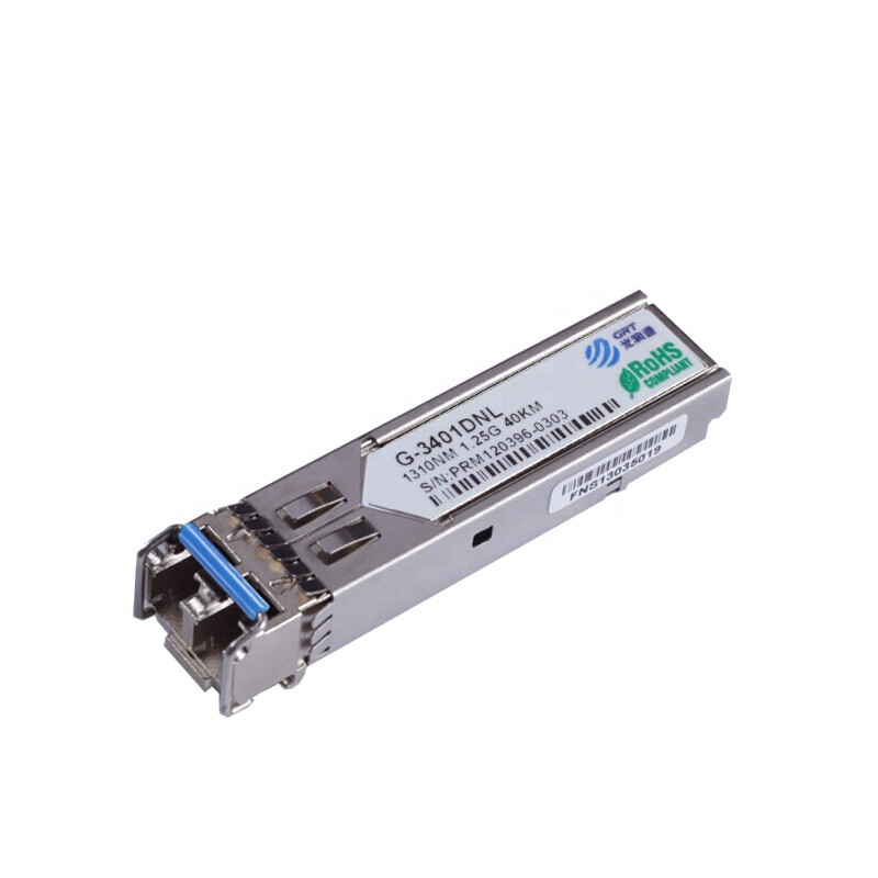
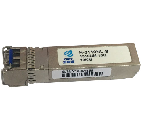
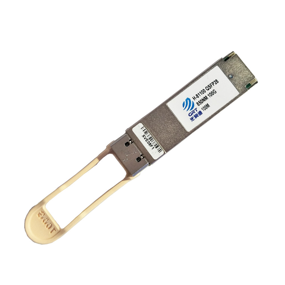
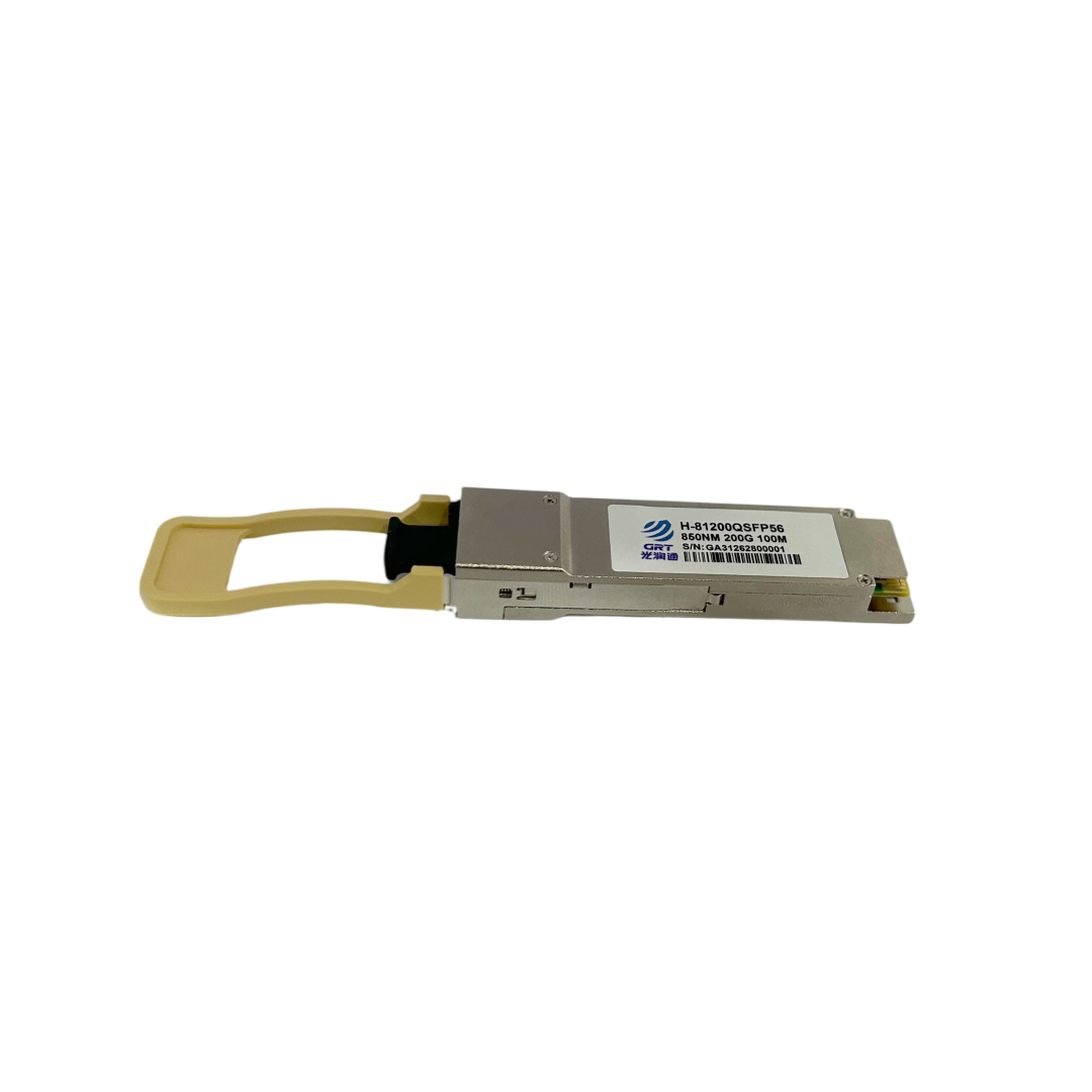
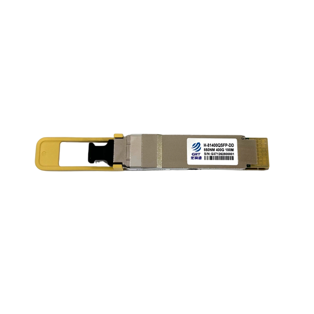
In real deployment, several layout practices greatly affect NIC cooling. First, tightly packed NIC installation: multi-GPU servers or high-density storage nodes often have fully populated PCIe slots. Adjacent NICs may only have a few millimeters gap, leaving middle adapters insufficient airflow over heat sinks and causing heat accumulation. When possible, install one NIC every other slot and reserve at least one empty slot. Second, NICs placed in airflow dead zones: some servers place PCIe areas behind hard disk backplanes or downstream of CPU heat sinks where airflow velocity drops sharply. Even with heat sinks, NICs cannot get adequate cooling. Before hardware selection or deployment, check the server airflow diagram and pick slots in primary airflow paths. Third, extra heat from optical modules: high-speed optical modules (especially 40G/100G SR4 modules) consume several watts. Dense ports fully populated with transceivers raise ambient temperature around NICs further. Remove unused optical modules if not required.
Modern enterprise NICs integrate built-in temperature sensors, readable via CLI tools or management software within operating systems. On Linux, ethtool -m (supported by certain drivers) or sensors commands can read real-time NIC temperature. Record steady-state NIC temperature under peak room temperature (e.g., partial AC failure in summer), compare against maximum operating temperature from datasheets to evaluate thermal margin. Proper slot selection, reserved gaps and temperature monitoring effectively prevent network degradation caused by overheating. Guangruntong (GRT) technical support assists customers with internal server layout assessment and temperature monitoring recommendations to optimize deployment plans.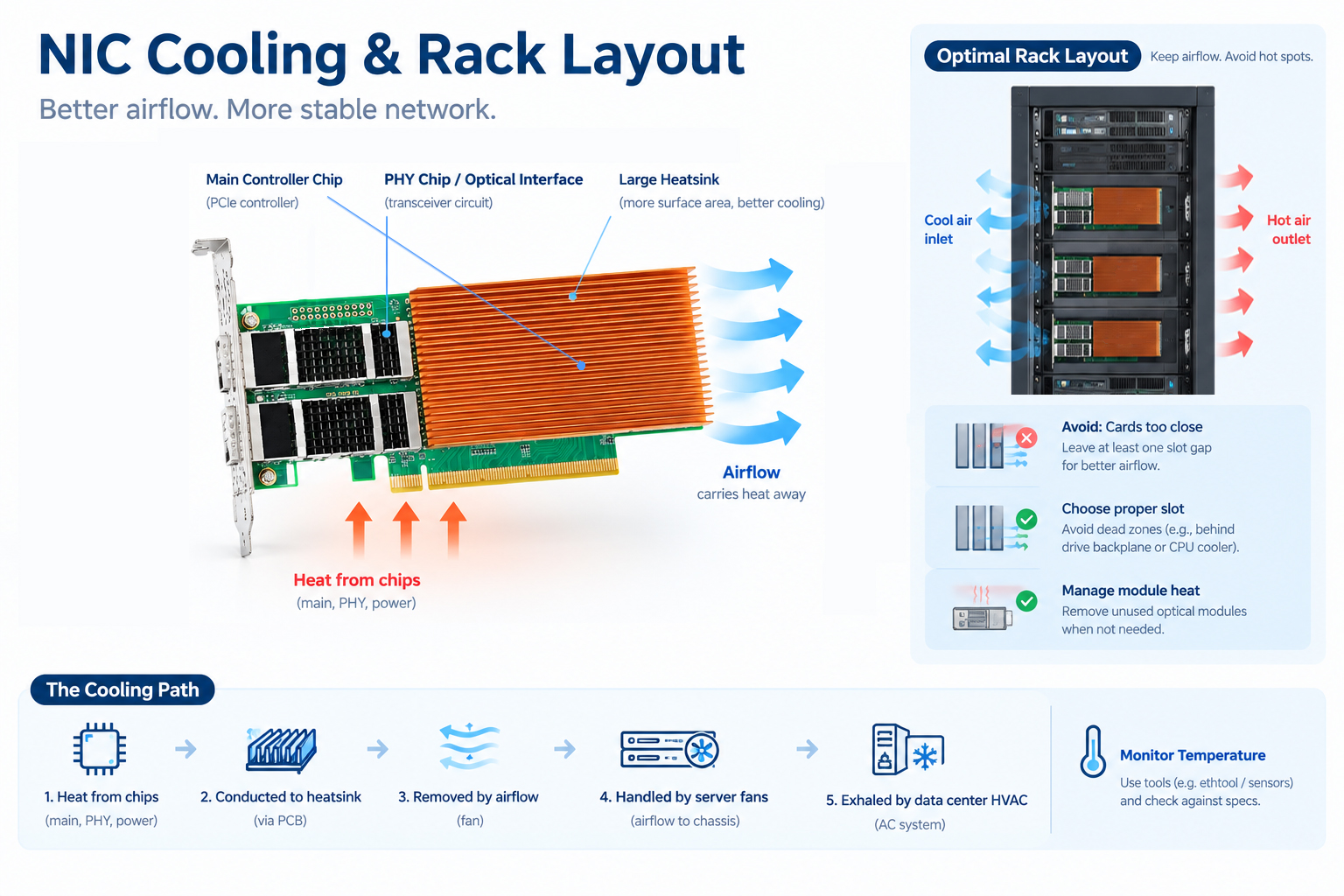
- Prev: Why are serpentine traces designed on the NIC PCB board
- Next: None
Latest information
- The Hidden Relationship Between NIC Heat Dissipation and Data Center Cabinet Layout
- Why are serpentine traces designed on the NIC PCB board
- NIC and Operating System Ecosystem Adaptation: From Hardware Compatibility to Win-Win Performance
- NIC Hardware Offload Technology: Let Server CPU Focus on Business Computing
- Network Card Driver: The Invisible Bridge Between Hardware and Operating System
- Understanding the Partners in Fiber Links: Optical Modules and Optical Fibers
- How to Select NICs for Virtualization Environments to Achieve Performance Isolation and Resource Allocation
- What are FCC, CE and RoHS on Network Cards