Sign in




AC Coupling Capacitors: Small but Essential Components in High-Speed PCIe Signaling
< BackAC Coupling Capacitors: Small but Essential Components in High-Speed PCIe Signaling
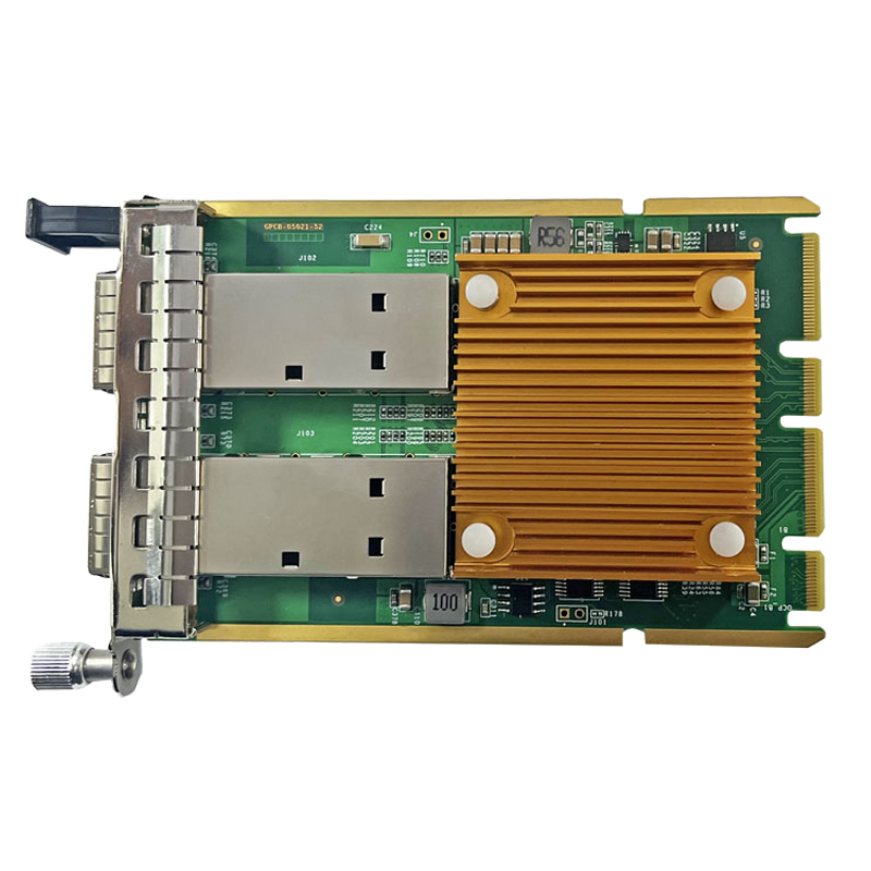
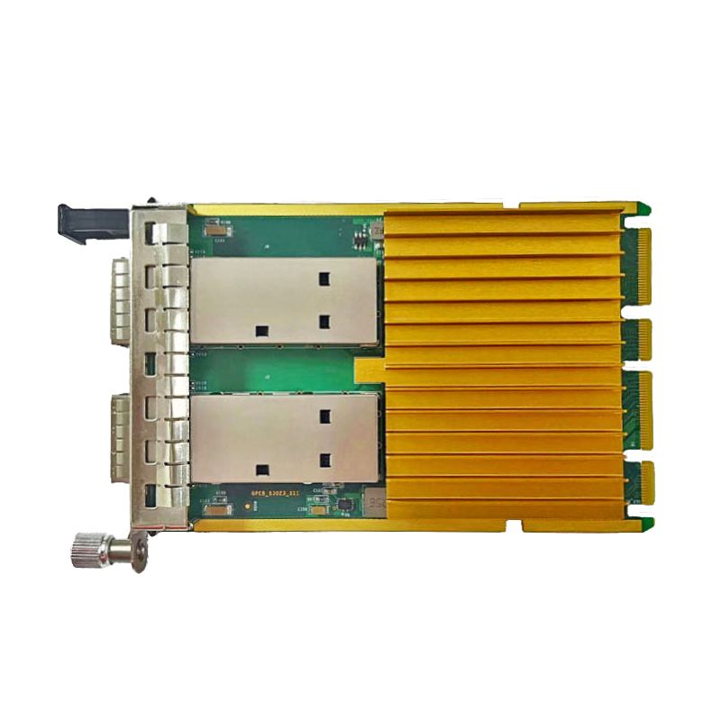
In the PCB design of fiber optic network adapters, there is a type of component that is tiny in size but indispensable: AC coupling capacitors distributed along PCIe high-speed signal lines. Although most users work with network adapters every day, they may rarely notice these capacitors, let alone understand the critical role they play in high-speed signal transmission.
I. What Are AC Coupling Capacitors?
An AC coupling capacitor, also known as a DC-blocking capacitor, is a capacitor connected in series with a high-speed differential signal channel. Its primary function is to filter out the DC component of a signal, allowing the AC signal to remain centered around the zero axis. To put it simply, the DC component is like a constant current flowing through a river, while the AC signal resembles ripples constantly changing on the water's surface. The AC coupling capacitor blocks the constant "DC flow" and allows only the "ripples" to pass through.
In a PCIe link, the transmitter and receiver may operate at different DC voltage levels. Without AC coupling capacitors, the DC potential difference between the two ends would be superimposed on the signal, potentially preventing the receiver from correctly identifying logic "0" and logic "1". By blocking the DC component, AC coupling capacitors allow devices with different voltage-level standards to connect directly, eliminating the need for complex level-shifting circuits.
II. Why Do PCIe Signals Require AC Coupling Capacitors?
The PCIe protocol explicitly requires AC coupling on all transmitter data lines. PCIe links use differential signaling to transmit data. Each differential signal consists of two signal lines, D+ and D-. The receiver determines whether the transmitter sends a logic "1" or logic "0" by comparing the voltage difference between these two lines.
If the common-mode voltages of the transmitter and receiver differ, this difference may affect the differential signal and shift the operating point of the receiver's comparator. AC coupling capacitors eliminate this offset by blocking the DC component. In addition, they can provide a degree of overvoltage protection by preventing abnormal DC voltage from flowing into and potentially damaging the receiver.
Regarding capacitance selection, different PCIe generations specify different value ranges. The PCIe 2.0 specification defines an AC coupling capacitance range of 75 nF to 200 nF. For PCIe 3.0, the range is 75 nF to 265 nF at 2.5 GT/s and 5 GT/s, and 176 nF to 265 nF at 8.0 GT/s. PCIe 4.0 and 5.0 require capacitance values ranging from 176 nF to 265 nF. In engineering practice, a 0402 package with a capacitance of 100 nF is one of the most commonly recommended combinations.
III. Where Should the Capacitors Be Placed?
The placement of AC coupling capacitors is an important PCB design detail. In theory, capacitors can be placed anywhere along the signal channel. In actual engineering practice, however, different protocols have different placement requirements: PCIe signals generally require AC coupling capacitors to be placed near the transmitter; SATA signals require them to be placed near the connector; and 10GBASE-KR signals require them to be placed near the receiver.
The PCIe protocol requires AC coupling at the transmitter. Therefore, in common engineering practice, the capacitors are placed close to the transmitting end. They should be positioned as close to the transmitter as possible rather than in the middle of the signal traces. Within each differential pair, the two capacitors should be arranged symmetrically.
Regarding package selection, the 0402 package is the preferred option. The 0603 package is also acceptable, but capacitor arrays are not recommended. Smaller packages have lower equivalent series inductance (ESL), which helps improve high-frequency signal transmission.
IV. AC Coupling Design in Guangruntong (GRT) Network Adapters
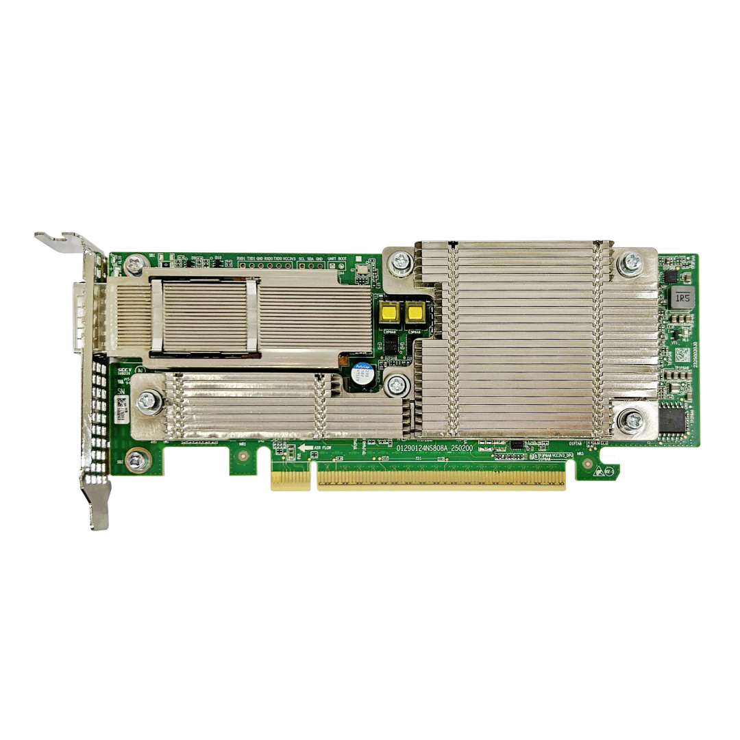
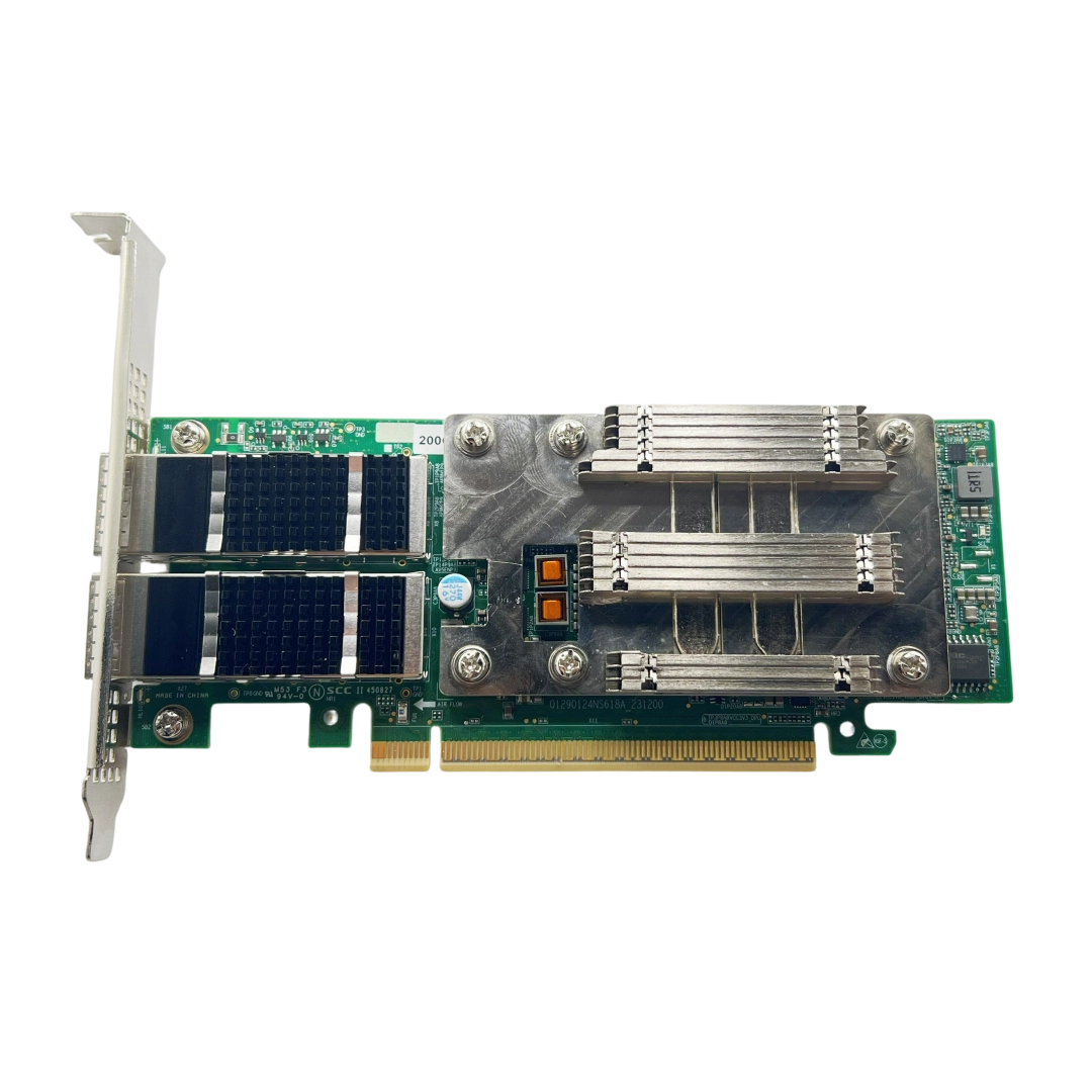
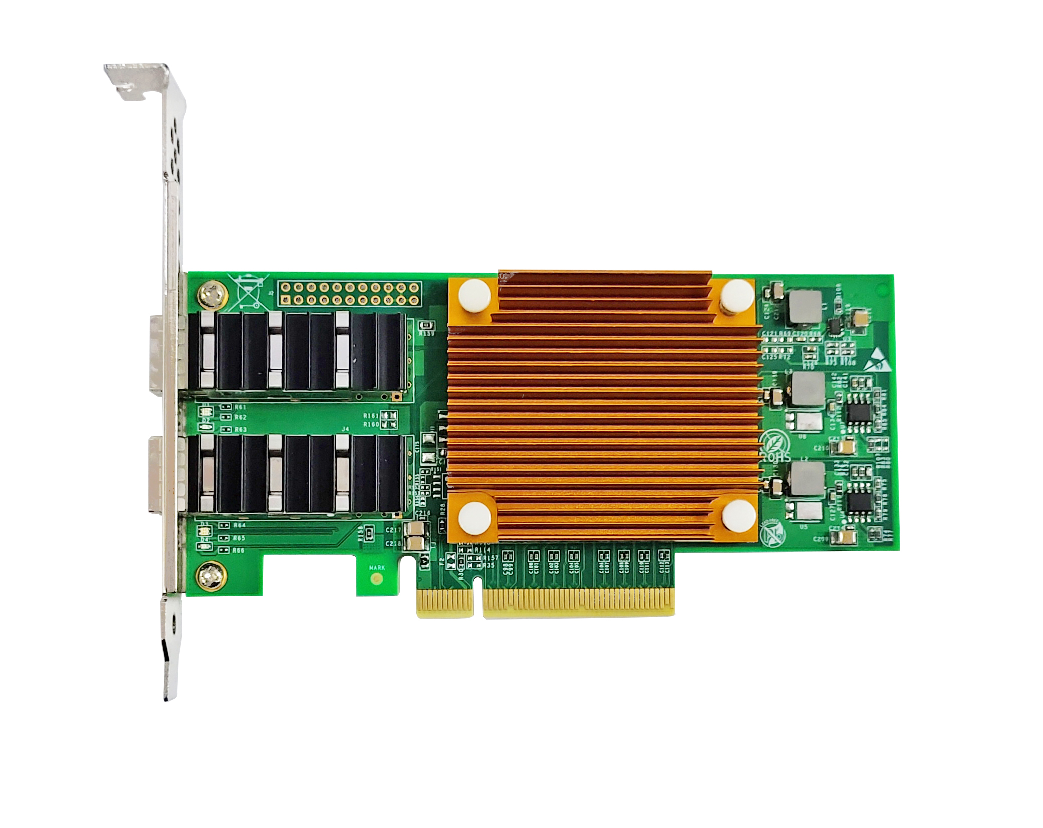
Guangruntong (GRT) strictly follows PCIe protocol requirements for AC coupling and widely accepted industry design practices in its network adapter PCB designs. During the schematic design stage, each fiber optic network adapter model is assigned an appropriate capacitance value in accordance with protocol requirements. Signal integrity simulations are also conducted to verify the suitability of capacitor placement and package selection.
During mass production, Guangruntong (GRT) implements strict incoming material inspections and SMT process controls to ensure consistent AC coupling capacitor specifications and reliable soldering on every network adapter, providing users with stable high-speed signal transmission.
Although AC coupling capacitors are only tiny components among the many parts on a network adapter, they play an irreplaceable role in high-speed signal transmission. It is precisely these often-overlooked design details that work together to provide the foundation for the stable operation of fiber optic network adapters.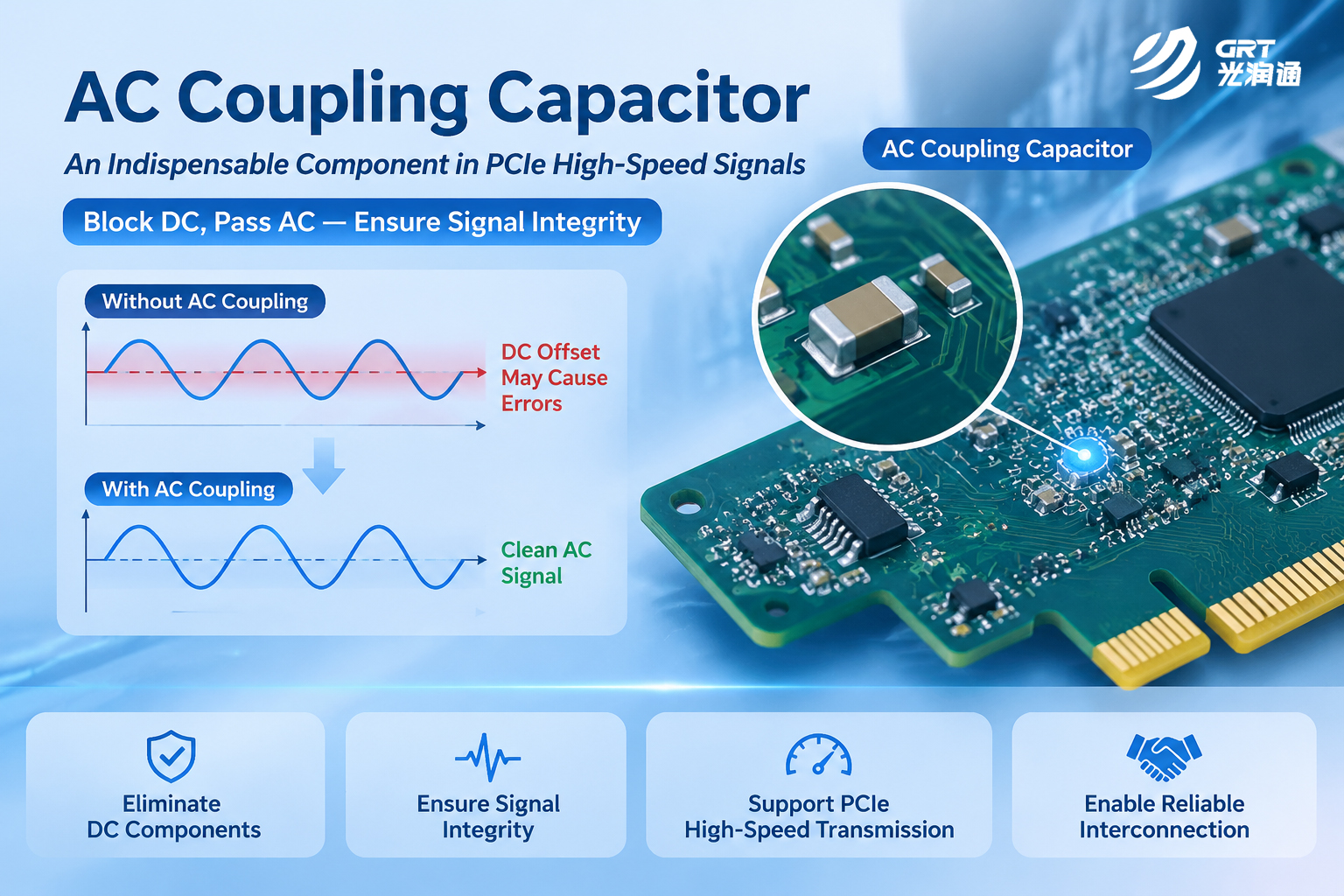
Latest information
- Core Differences Between NIC Redundant Link Functionality and Bypass NICs
- How to Monitor Laser Bias Current to Predict Optical Module Aging
- What Is the Normal Transmit Optical Power of a 10G Optical Transceiver? A Look at the Guangruntong (GRT) H-3410FNL-S
- AC Coupling Capacitors: Small but Essential Components in High-Speed PCIe Signaling
- GRT 200G Multimode Optical Transceiver
- Network Troubleshooting
- Wavelength Division Multiplexing: Enabling Fiber Optics to Carry More Data
- How PCIe Interfaces Affect Signal Integrity